Related research on the heat dissipation mode of cylindrical power battery
Through a brief introduction to the cylindrical power battery module, it pays attention to the heat dissipation method of the battery, and analyzes some specific cases.
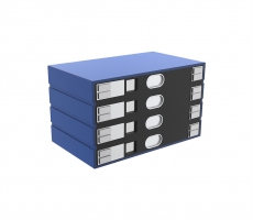
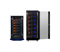
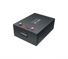
Among the three main types of power batteries, although cylindrical batteries do not have the largest market share, their commercialization and standardization are the most mature due to their extensive use in the consumer goods market. After years of precipitation, the process is stable and consistent. Cylindrical batteries made of ternary materials have an energy density of 210~250Wh/kg. Large-scale standardized batteries make the modules also have the prerequisite for automated production. Cylindrical battery is small in size, which is very suitable for the battery pack box with irregular space, and can make full use of the corner space. Although the current 18650 is facing the problem of being replaced by the 21700, the 18650 will still have its own place for a period of time on small-scale, complex-shaped, low-cost and more sensitive vehicles. Module basic structure In the cylindrical battery cell module design, the module structure is diverse, which is mainly determined according to the needs of customers and models, which ultimately leads to different manufacturing processes of the modules. The module is generally composed of battery cores, upper and lower brackets, bus bars (some are also called connecting pieces), sampling wiring harness, insulation board and other main components, as shown in the figure below.
Structural design The structure design of cylindrical battery module, its purpose is to fix multiple cylindrical batteries in a designated position to ensure that no excessive displacement occurs under reasonable vibration and shock conditions. The position of the cell is determined by the cell bracket. In extreme cases, the cell bracket may be deformed. In order to maintain the distance between the cells, a separate design of high temperature resistant and low-quality telecom spacers is generally designed. The black part in the middle of the JAC iEV5 module in the picture below should be the design intent of this type.
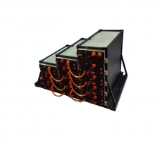
Inside the cylindrical battery module, parallel connection is relatively easy to achieve, as long as a busbar connects one pole of the cell, but to achieve a uniform current density distribution and a uniform thermal field, it is a place to test the level of the engineer. Generally, it is designed to be a more symmetrical structure as much as possible, but the position of the module inlet and outlet is always different from the uniform arrangement of other batteries, so it is a key point of design simulation. Like Tesla, the bizarre shape of the parallel busbar design should be the result of heat and current distribution calculations (the Tesla module is found in the second half of the article). Introduction to the cooling method of power battery module Currently, liquid cooling and phase change material cooling are more discussed. The typical liquid cooling module of cylindrical battery cell is Tesla, which will be introduced in the following examples. The pure liquid cooling system is to place the components with good heat conduction close to the cell, and remove the excess heat generated during the working process of the cell as evenly and efficiently as possible. Liquid cooling can operate completely independently like Tesla, or it can be combined with other cooling methods. One of the important forms is to combine with thermal silica gel, as shown in the figure below. Thermally conductive silica gel can achieve a tighter fit than metal contact with metal, thereby obtaining better heat transfer performance.
The heat generated when the battery cell works is transferred to the liquid cooling tube through the thermally conductive silicone gasket, and the heat is carried away by the free circulation of the coolant thermal expansion and contraction, so that the temperature of the entire battery pack is uniform and uniform, and the strong specific heat capacity of the coolant absorbs the battery cell The heat generated during work makes the entire battery pack operate at a safe temperature. The thermal silica gel has good insulation properties and high resilience, which can effectively avoid the vibration and friction damage between the cells and the hidden danger of short circuits between the cells. It is the best auxiliary material for water cooling solutions. This liquid cooling solution uses an S-shaped thermally conductive aluminum tube and attaches a special-shaped thermally conductive silicone tape to the aluminum tube (adding convex stripes on the contact surface of the thermally conductive silicone tape and the battery core) to make the contact surface between the battery core and the heat conductive tube larger. The heat conduction effect and shock absorption effect are better. Cylindrical battery cell module PCM heat dissipation structure, the application of phase change material, can be used with liquid cooling, or can be used independently. Stand-alone applications can have multiple arrangements. The PCM sheet can be attached to the outside of the battery module to assist in heat dissipation, as shown in the figure below. According to the experimental results, the presence of phase change materials can also play a role in cooling.
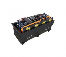
The most efficient method is naturally the method with the largest contact area between the battery cell and the PCM. Examples are as follows.
Phase change materials are used for thermal management battery packs. First, calculate the quality of the PCM needed, and then determine the geometric size of the phase change material matrix according to the shape of the battery, make the phase change material matrix, and evenly dig out the single cells on the matrix For holes of the same size, the number of holes is determined by the number of single cells that can be accommodated in the battery module. The application of this form of phase change material objectively prevents the transmission of thermal runaway monomer energy, and is considered to be an ideal form of thermal management. The basic requirements of power battery application scenarios for phase change materials: low phase change temperature, need to adapt to the best operating temperature range of lithium batteries 15℃-35℃; material phase change temperature can be adjusted within a small range, the best for different types of batteries The working temperature range is not completely consistent; the material shape, before and after the phase change, it is best not to have a liquid gas phase; material latent heat is large, the system has a strong constant temperature ability; heat transfer coefficient must be high in order to maintain a uniform temperature; material has good insulation. Avoid the risk of insulation leakage in the high-voltage system. The phase change material has a low mass density, which reduces the impact on the energy density of the battery pack. Even if the above conditions are met, the application of phase change materials still has limitations. When the environment is extremely harsh, such as the temperature is too high. The ability of the phase change material to absorb heat is limited. When the phase change is completed, the system temperature naturally rises. When the temperature is too low and too low for a long time, the cold start of the vehicle must absorb external energy to heat it. Cylindrical cell module manufacturing
Figure 2-2 Schematic diagram of the cylindrical cell module structure 1) Cell sorting, module process design needs to consider the consistency of the electrical performance of the module to ensure that the overall performance of the Pack meets or meets the requirements of the vehicle. In order to ensure the consistency of the electrical performance of the modules, strict requirements must be imposed on the incoming materials of the batteries. Batteries manufacturers generally group the batteries according to their voltage, internal resistance and capacity specifications before they are shipped. However, the final requirements of battery manufacturers and pack manufacturers are different, taking into account the manufacturing process, cost, and battery. For factors such as performance, Pack manufacturers generally re-sort the cells according to their own standards. Cell sorting needs to consider the issue of sorting standards. A reasonable standard will reduce the remaining idle cells, improve production efficiency, and reduce production costs. In the actual production process, it is also necessary to check the appearance of the battery core, such as checking whether the battery core has defective products such as damage to the insulating film, warping of the insulating film, leakage of the battery, and stains on the positive and negative end faces.
Typical cylindrical battery cell module process flow diagram 2) The battery core is inserted into the lower bracket, and the battery core into the lower bracket refers to inserting the battery core into the battery core positioning hole of the lower bracket. The difficulty lies in the matching tolerance between the battery core and the lower bracket hole. The hole is too large to facilitate the insertion of the battery core, but the battery is not fixed well, which affects the welding effect; the hole is too small, and the battery core is difficult to insert into the lower bracket positioning hole, serious It may cause the battery core not to be inserted and affect the production efficiency. In order to facilitate the insertion of the battery core and fix the battery core, the front end of the lower bracket hole can be opened into a bell mouth.
Schematic diagram of the lower bracket opening the bell mouth 3) Cell polarity judgment. Cell polarity judgment refers to checking whether the polarity of the cell meets the requirements of the document, which is a safety inspection. If there is no polarity check and the cell polarity is reversed, the module will be short-circuited when it is installed on the second side of the bus bar, resulting in damage to the product and serious personal injury. 4) Cover the bracket. Covering the bracket means to cover the upper bracket on the cell and fix the cell in the bracket. Under normal circumstances, it is more difficult to cover the bracket than the battery cell to enter the lower bracket. One is related to the production process of the cylindrical battery. There is a rolling groove process in the process. The upper bracket may not be able to be covered in serious cases; secondly, the battery core and the lower bracket are not fixed well, resulting in a certain skew of the battery core, and the upper bracket is not easy to cover or cannot be covered. 5) Module spacing detection. Module spacing detection refers to the detection of the distance between the end face of the cell pole and the surface of the bracket. The purpose is to check the degree of cooperation between the end face of the cell pole and the bracket to determine whether the cell is fixed in place. Whether to meet the welding conditions to determine in advance whether to meet the welding conditions. 6) Cleaning. Plasma cleaning is a dry cleaning, which mainly relies on the "activation" of active ions in the plasma to remove stains on the surface of the object. This method can effectively remove dirt, dust, etc. on the end face of the cell pole, and prepare for resistance welding in advance to reduce welding defects. 7) Busbar installation. Busbar installation refers to fixing the busbar to the module for resistance spot welding. When designing, it is necessary to consider the position accuracy of the bus bar and the battery core, especially the positioning reference, the purpose is to make the bus bar position in the center of the pole surface of the battery core, which is convenient for welding. When designing the upper and lower brackets, consider the isolation of the busbars; if the isolation design is not good, you need to consider the use of anti-short-circuit tooling in the process design to avoid short-circuits under abnormal conditions. 8) Resistance welding, resistance welding refers to welding the bus bar and the pole surface of the cell together by means of resistance welding. At present, resistance spot welding is generally adopted in China. When designing the resistance spot welding process, the following 4 points need to be considered: (1) the material, structure and thickness of the bus bar; (2) the material, shape, Front end diameter and grinding frequency; (3) optimization of process parameters, such as welding current, welding voltage, welding time, pressure, etc.; (4) cleanliness and flatness of the welding surface. In actual production, there are many failure factors, which require technical personnel to analyze and deal with the actual situation. 9) Welding inspection. During the resistance welding process, the equipment generally monitors the welding parameters. If abnormal parameters are detected, the equipment will automatically alarm. Since there are many factors that affect welding quality, only parameter monitoring is used to judge welding failure. The current results are not particularly ideal. In the actual production control, the welding effect is generally checked and confirmed again by manually inspecting the appearance and manually provoking the bus bar. 10) Glue, in the application of modules, there are generally two uses for glue: one is to fix the battery, which mainly emphasizes the adhesive strength, shear strength, aging resistance, life and other performance indicators of the glue; the other is The heat of the battery core and the module is transferred out through the thermal conductive glue, which mainly emphasizes the thermal conductivity of the glue, aging resistance, electrical insulation, flame retardancy and other performance indicators. Due to the different uses of the glue, the properties and formula of the glue are also different, and the methods and equipment for realizing the glueing process are different. In terms of glue selection and gluing process, the following 3 points need to be considered: The safety and environmental performance of glue: Try to choose non-toxic and odorless glue, which can not only protect the operator, but also protect the user, and better protect the environment. , Is also the goal of new energy development. B Surface drying time of glue: In order to improve production efficiency, it is generally hoped that the surface drying time of glue is as short as possible. In the actual production process, if the glue meter drying time is too short, due to factors such as material waiting and equipment abnormality, a large amount of glue will be wasted; it may also be caused by the operator not handling in time, and the equipment will be blocked due to the short curing time of the glue. When the cable is stopped. According to experience, it is reasonable to control the surface drying time to 15~30min as much as possible. C The amount of glue: The amount of glue is mainly determined by the product and process, and the purpose is to meet the requirements of the product. At present, the commonly used gluing processes are glue, gluing, spraying and potting, and the equipment required for each process is also different. It is necessary to pay attention to the control of the amount of glue when making glue to avoid overflow of glue and affect other processes. 11) Cover insulating plate, which means to insulate and protect the busbar of the module. When designing the process, it is necessary to pay attention that the insulating board cannot be higher than the upper edge of the support, and the gap between the insulating board and the frame of the support is preferably less than 1mm. 12) Module EOL test, EOL test (endofline) (generally called offline test) is a key part of quality control in the production process. It mainly tests the special characteristics of the module. The main test items are: a Insulation withstand voltage test ; B internal resistance test; c voltage sampling test; d size detection; e appearance inspection. Test items are generally increased or decreased according to the requirements of customers and products, among which safety test items are indispensable. 13) Transfer to Pack assembly or storage, and modules that have passed the EOL test are transferred to Pack assembly process or storage according to regulations. During the transfer process, the module needs to be insulated and protected to prevent the module from falling. Through the introduction of the production process of the cylindrical battery cell module, the design of the process is different for different customers and products, and the purpose is to quickly respond to the needs of customers and the market. When designing the module process flow, generally the following points need to be considered: 1) Safety: product safety and safe production; 2) Electrical performance: capacity, voltage, internal resistance, consistency of performance; 3) Production cycle: beat The higher the value, the greater the production capacity; 4) Dimensions: external dimensions and fixed dimensions; 5) Process route: refers to the selection and determination of key processes; 6) Cost: factors that need to be considered in both product design and process design. Through the above analysis, it is not enough to design the module process flow well. It also needs a complete production system to support it in order to produce products that satisfy customers. As a R&D designer, if you can understand the production capacity of your system in detail, you will get twice the result with half the effort. Well-known vehicle power battery module case TeslaModelS, using cylindrical 18650 lithium batteries, the first thing that comes to mind is of course the most popular Tesla, although Tesla seems to be not doing well recently. The Roadster, ModelS, and ModelX models are all driven by 18650 battery packs, and the Model3 was upgraded to 21700. Take ModelS as an example. Let's take a look at the 18650 module. Maybe you have seen a lot of it on the Internet. Here is also the information compiled from the Internet, so I will talk about it. battery pack
Module
The red line marked in the first picture above is the dividing line of 6 small modules in a module. A partition is installed on the dividing line to separate the 6 parts to avoid thermal runaway in one part, and the rest It is spread too quickly, causing violent heat and even explosion in a short time. The partition is shown in the figure below.
Model S85 has a total of 16 battery packs, each module contains 444 batteries, each of which is connected in parallel to form a group. The entire battery board is made up of 6 groups of batteries in series. It can be calculated that there are a total of 7,104 18650 lithium batteries on this TeslaModelS85. Each cell has a pole connected to the parallel busbar through a fuse. The thin silver wire in the figure below is the fuse of each cell.
did not see the connection between each small module inside the module.
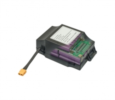
A module controller circuit board is installed on the side of each module, as shown in the figure below.
circuit board close-up
An exploded view of the battery pack shown in the picture below, in which the brown part shows the overall shape of the water cooling pipe. It is said that the disassembled Tesla battery packs circulating on the Internet are only