What is BMS?
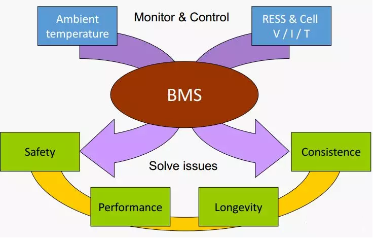
Battery Management System (BMS) is a system that manages lithium batteries. It usually has the function of measuring battery voltage, current and temperature to prevent or avoid abnormal conditions such as over-discharge, over-charge and over-temperature of lithium battery.
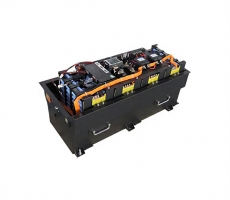
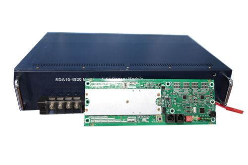
SES Power attaches great importance to BMS because BMS is the brain of Li-ion battery pack, especially large Li-ion battery pack, and its performance and reliability determine the overall performance of Li-ion battery pack.
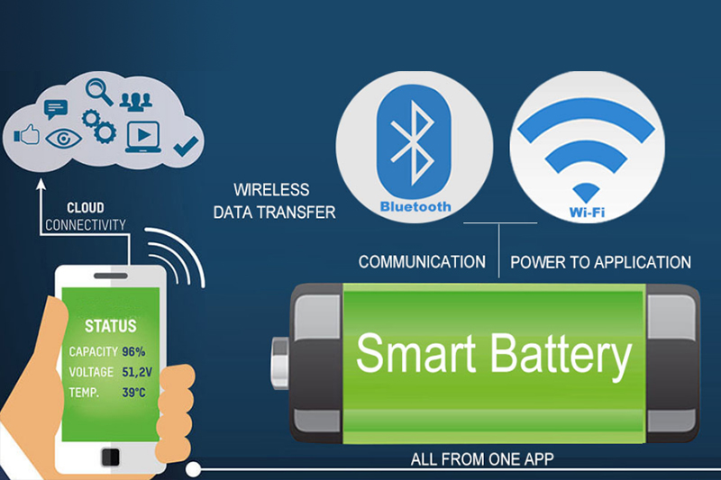
Some advanced Li-ion battery BMS management systems have accurate charge state estimation function, RS485 communication function, CAN communication function, Bluetooth communication function or remote network online monitoring function.
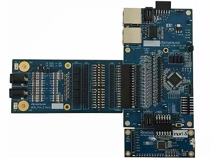
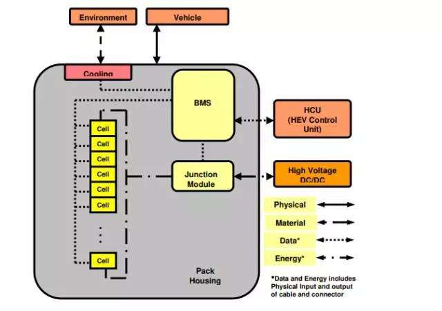
BMS battery management system unit includes BMS battery management system, control module, display module, wireless communication module, electrical equipment, battery pack used to power the electrical equipment and collection module used to collect battery information from the battery pack.
The BMS battery management system is connected to the wireless communication module and the display module respectively through the communication interface, the output of the acquisition module is connected to the input of the BMS battery management system, the output of the BMS battery management system is connected to the input of the control module, the control module is connected to the battery pack and the electrical equipment respectively, the BMS battery management system is connected to the Server through the wired/wireless communication module Server side
What are the functions of BMS?
Even if two single cells produced in the same batch are affected by production process errors, differences in use environment and other factors, their performance cannot be exactly the same. In the process of use, this inconsistency will gradually expand, and the danger of overcharging, overdischarging and local overheating may occur, which seriously affects the service life and safety of the battery pack.
This is when the BMS comes into play. So what does BMS mainly do?
A: Battery monitoring
In the process of battery charging and discharging, the voltage, temperature, current and total system voltage of each battery are collected in real time to prevent the battery from overcharging or over discharging.
At the same time, it can give the battery condition in time and select the battery with problems to keep the reliability and efficiency of the whole battery operation.
In addition to this, the usage history file of each battery should be established to provide information for further optimization and development of new types of electricity, chargers, motors, etc., and to provide a basis for off-line analysis of system failures.
B: Battery protection
After the BMS collects enough data, it will provide the necessary protection for the battery according to the data, so that the battery works in a safe environment, mainly including voltage and current control during charging and discharging, as well as temperature management.
C: Battery state estimation
Next is an estimate of the battery state based on previous data, such as SOC, SOH, these data are not directly measured, need to be through some other methods, simple, such as the use of voltage changes to characterize the capacity, but this is often inaccurate, because the voltage curve of battery charging and discharging in a certain range is almost flat, which leads to a large error; more complex A little more complex is the use of the voltage and current according to the charge and discharge time to integrate to find, will be a little better than the previous; then there are some Kalman filter algorithm to achieve, which is a good algorithm can be used to predict, it also takes into account a variety of noise; there is now a hot neural network, the use of AI to manage.
D: Battery balancing and performance maximization
The BMS will also analyze all the data to specify different equalization strategies to equalize the single battery, so that the battery pack will reach a balanced and consistent state for each cell. The ultimate goal is to charge as full as possible and discharge as much as possible.
E: Feedback to users or external devices
Finally, the BMS is to communicate with the outside world based on monitoring and recording data, generally through RS485 or CAN bus to communicate with our other ECU.
In general, SES Power believes that BMS actually solves two things, the first is safety, to ensure that the battery has a good working environment, so that individual batteries are not always in a dangerous state and thus lead to serious consequences; the second is high efficiency, so that each single battery can play its maximum value and produce the highest benefit.
How is BMS classified?
After understanding the definition of BMS and the basic functions of BMS, SES Power will make a general classification of BMS according to the different functions and architectures
A: Classification according to function
It can be roughly divided into general BMS, energy storage (ESBMS), and power (Power BMS)
A1: Centralized BMS
This is a very common type, SES Power is used in many projects is this kind of BMS, this kind of BMS is on the basis of PCM, increased SOC, SOH, RS485, Bluetooth, CAN and other basic communication protocols, the content is relatively simple, but also enough for the end customer to have a deep understanding of the parameters of lithium batteries.
This kind of BMS is generally used in single-string, dual-string and multi-string, such as 12V LFP battery pack, 24V LFP battery pack, 36V LFP battery pack, 48V LFP battery pack and so on customized Li-ion battery pack.
Centralized BMS has the advantages of low cost, compact structure and high reliability, and is generally common in scenarios with low capacity, low total voltage and small battery system size, such as power tools, robots (handling robots, booster robots), IOT smart home (sweeping robots, electric vacuum cleaners), electric forklifts, electric low-speed vehicles (electric bikes, electric motorcycles, electric sightseeing cars, electric patrol cars, electric golf carts, etc.), and light hybrid vehicles.
A2: Energy Storage BMS
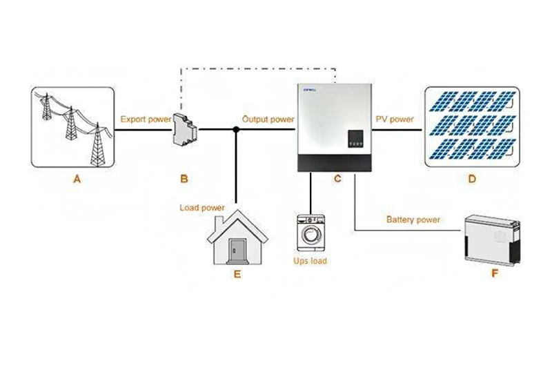
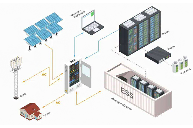
Energy storage battery management system, referred to as ESBMS. The energy storage system is a very large system, and it often needs to communicate and control many large devices. In the energy storage system, the energy storage battery only interacts with the energy storage converter in terms of high voltage. The converter takes power from the AC grid to charge the battery pack; or the battery pack supplies power to the converter, and the electrical energy passes through the converter. Converted to AC and sent to the AC grid.
ESBMS mainly has an information interaction relationship with the converter and the dispatching system of the energy storage power station. On the one hand, the battery management system sends important status information to the converter to determine the high-voltage power interaction; on the other hand, the battery management system sends the most comprehensive monitoring information to the dispatching system PCS of the energy storage power station.
The communication between ESBMS and internal basically adopts CAN protocol, but its communication with external (mainly refers to the energy storage power station dispatching system PCS) often adopts the Internet protocol format TCP/IP protocol.
For the sake of safety and economy, the energy storage system often chooses lithium iron phosphate when choosing lithium batteries, and the energy storage system is often in a remote location, so in the case of higher cost performance requirements, the stability is very important decisive factor.
A3: Power-type BMS
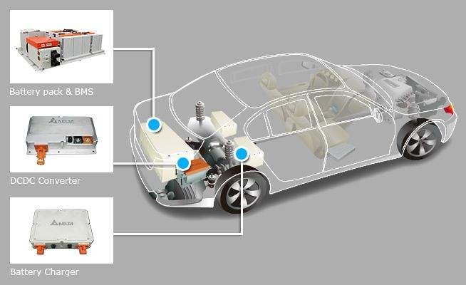
This generally refers to the BMS used in electric vehicles. In addition to the general BMS functions, compared with other types of BMS, because the power battery system is in a high-speed electric vehicle, the power response speed and power of the battery Characteristics, SOC estimation accuracy, and the number of state parameter calculations all have higher requirements.
At the same time, the power BMS also pays special attention to
1) Safety, protect battery cells or battery packs from damage and prevent safety accidents;
2) Durability, make the battery work in a reliable safe area and prolong the service life of the battery;
3) Power, keep the battery working in a state that meets the requirements of the vehicle.
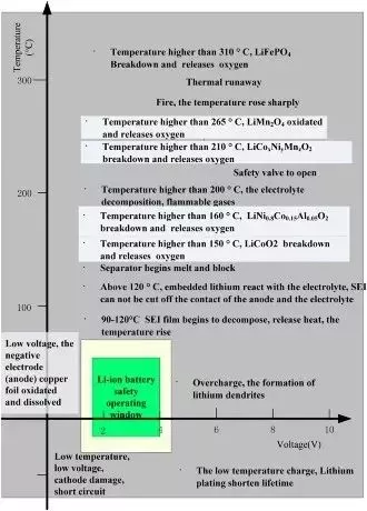
Fig: Safe working area for lithium-ion batteries
The power battery, the electric vehicle environment in which it is located, adopts the CAN protocol, but the internal CAN is used between the internal components of the battery pack, and the vehicle CAN is used to distinguish between the battery pack and the whole vehicle.
B: Classification by topology
Topology is important for BMS because it affects system cost, reliability, ease of installation and maintenance, and accuracy of measurement predictions.
B1: Centralized
The centralized type, also called the integrated type, encapsulates the entire BMS in one device, and uses many wires to connect the batteries at different potentials.
The advantages of this architecture are very obvious. First, the structure is compact, and then the price is relatively cheap. Of course, the maintenance is relatively simple, and it is often enough to replace the whole. However, there are also many disadvantages: the first is poor scalability, a product needs to be redesigned if it wants to expand, and the second is safety hazards, because the wiring harness is too long and it will cause a series of safety hazards.
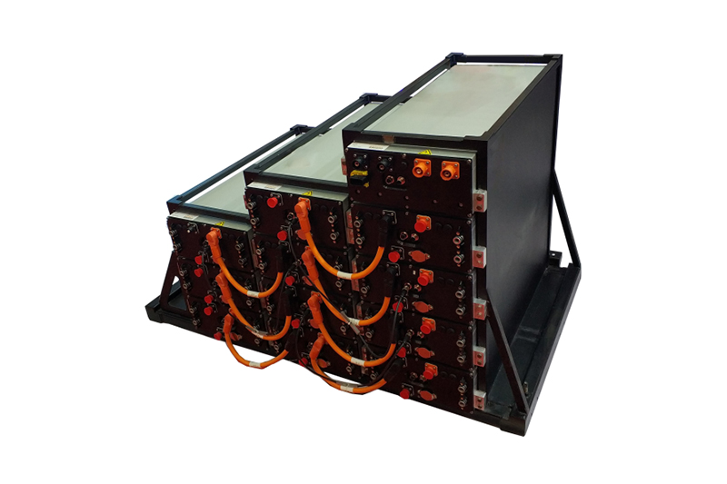
B2: Modular
The next architecture is modular. This architecture is very similar to the centralized BMS, but the modular BMS is divided into many identical sub-modules, and the wires of each package will connect different parts of the entire panel to monitor a certain area.
One module is assigned as the main module to manage and dispatch the entire battery pack and to communicate with the outside world. Other slave BMSs communicate with the master BMS through the communication bus.
The advantages of this architecture are: First, because it is equivalent to miniaturizing the centralized BMS and multiple cascades, it has most of the advantages of centralized, such as easy maintenance, low price, etc.
Secondly, due to the small scale of a single module, the wires from the sub-module to the single battery are relatively short and can be closer to the battery, thus avoiding the hidden dangers and errors caused by excessively long wires.
Finally, it is also easy to expand, the advantage of which can easily add more submodules to achieve expansion.
But it also has some disadvantages:
The first is the need to add extra wires. Compared with the centralized type, the modular stepper needs to be connected to the battery pack, and each module also needs to be connected with wires.
Secondly, the cost is high. The main reason is that the functions of each module are the same, but not all functions are used, which causes waste, especially the subordinate modules, which actually use not many functions.
In fact, we also feel that this structure is not particularly reasonable when we see it here, so there is an improved version.
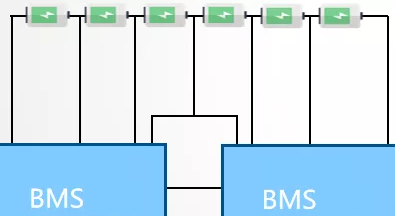
B3: master-slave
We separate the modules according to their master and slave functions.
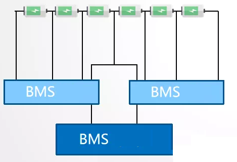
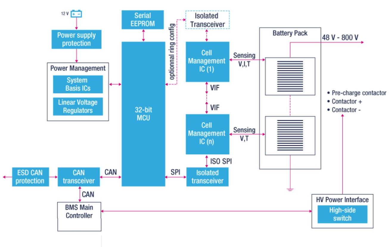
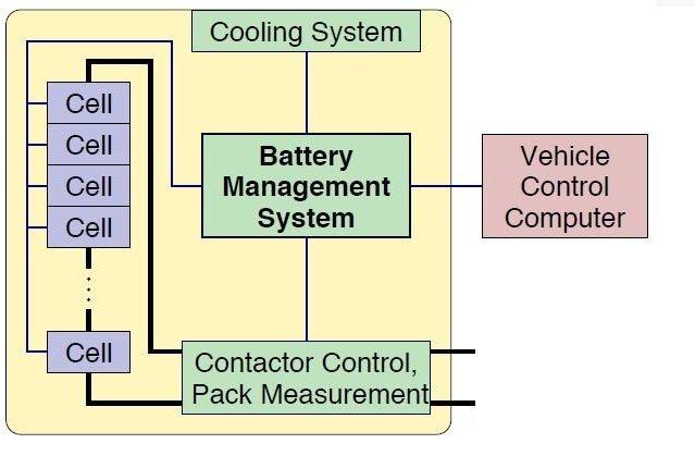
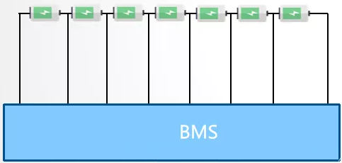
Figure: Electronic Architecture of Master-Slave BMS
Functions that are not used by the module will be removed, so that the cost can be reduced. The master BMS is responsible for relatively many functions, including calculation, prediction, decision-making, communication, etc. The slave unit is basically only responsible for measurement. It can be said that it inherits most of the advantages of the modular structure, while also reducing the cost of expansion.
B4: Distributed
There is also a topology, slightly different from what we talked about earlier, called distributed.
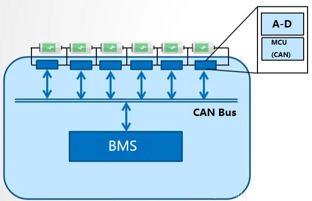
In the previous topologies, various electronic devices are not installed on the single cell, and they are basically measured by wire throwing. However, in a distributed system, our measurement unit and other electronic equipment are directly installed in the circuit board integrated with the single cell. The advantage of this is that there is basically no connection between the BMS and the single cell. Then, similar to the master-slave type, there will also be a controller responsible for operations, predictions, decision-making, etc.
Communication between modules is based on the bus. In the car, we generally use the CAN bus. Each unit contains an acquisition loop, and the MCU with CAN bus can send and receive information directly through bus communication.
It has many advantages of course:
The first is to have extremely high scalability, which can be refined to the expansion of single cells.
Secondly, the connection reliability is high, there are basically no excessively long cables, and the battery and the measurement circuit are closely combined, which also reduces interference and errors. Security is also high.
It is also easy to maintain, and only a small unit needs to be replaced if something breaks.
But there are also some shortcomings:
First of all, the cost is very high, because each unit adds a set of equipment, so the overall cost is very high.
The second is that the volume is too large, which is also well understood. There is a measurement system next to each cell of each battery, which will affect the volume of the entire battery panel. Now some ICs can be made very small, and this influencing factor will become less and less.
The Core Technology Of The Best BMS?
BMS is the core component of lithium batteries, especially energy storage systems, electric vehicles and other products that need to be applied to large-scale battery combinations. Its importance is beyond doubt.
Many BMS manufacturers on the market claim to have their own so-called core technology, and some new terms keep popping up, which even the SES Power team, with over 20 years of experience in the industry, has a headache.
According to the understanding of senior engineers of SES Power, in addition to general parameters, such as detection speed, detection range, control ability, withstand voltage value, layout, etc., the following points are the real core of BMS.
A: We must be clear that the BMS system usually includes a detection module and a calculation control module.
Detection refers to measuring the voltage, current and temperature of the battery cell and the voltage of the battery pack, and then transmitting these signals to the computing module for processing and issuing instructions. So that the computing control module is the brain of BMS. The control module generally includes hardware, basic software, runtime environment (RTE) and application software. The core part-application software.
The function of the software is generally divided into two parts: the estimation algorithm of the battery state, the fault diagnosis and the protection.
State estimation includes SOC (State of Charge), SOP (State Of Power), SOH (State of Health), balance and thermal management. Battery state estimation is usually to estimate SOC, SOP and SOH. SOC simply means how much power is left in the battery; SOC is the most important parameter in BMS, because everything else is based on SOC, so its accuracy and error correction capabilities are extremely important. If there is no accurate SOC, no amount of protection function can make the BMS work normally, because the battery will always be in a protected state, and it will not be able to extend the life of the battery.
In addition, the estimation accuracy of SOC is also very important. The higher the accuracy, the higher the cruising range for the same capacity battery. Therefore, high-precision SOC estimation can effectively reduce the required battery cost. For example, the Fiat 500e BEV of Chrysler can discharge SOC=5% all the time. It became the electric car with the longest cruising range at that time.
The accurate estimation of SOP can maximize the utilization efficiency of the battery. For example, when braking, it can absorb as much energy as possible without harming the battery. When accelerating, it can provide more power to obtain greater acceleration without harming the battery. At the same time, it can also ensure that the car will not lose power due to undervoltage or overcurrent protection during driving, even when the SOC is very low.
In this way, the so-called primary protection and secondary protection are incidental products in the face of precise SOP. Not that protection is not important. Protection is always needed. But it cannot be the core technology of BMS.
For low temperature, old batteries and very low SOC, accurate SOP estimation is especially important. For example, for a group of well-balanced battery packs, when the SOC is relatively high, the SOC difference between each other may be very small, such as 1-2%. But when the SOC is very low, the voltage of a certain cell will drop rapidly. The voltage of this battery cell is even more than 1V lower than the voltage of other batteries. To ensure that the voltage of each cell is not lower than the minimum voltage given by the battery supplier, SOP must accurately estimate the maximum output power of the cell whose voltage drops rapidly at the next moment to limit the use of the battery and protect the battery.
The core of estimating SOP is to estimate each equivalent impedance of the battery online in real time.
SOH refers to the state of health of the battery. It includes two parts: changes in capacity and power. It is generally believed that when the capacity decreases by 20% or the output power decreases by 25%, the battery life is reached. However, this does not mean that the battery can no longer be used.
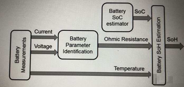
For a pure electric vehicle EV, capacity estimation is more important, because it is directly related to the cruising range, and the power limit is only important when the SOC is low. The requirement for SOH also requires both high precision and error correction capability. And SOH without error correction capability is meaningless. The accuracy is less than 20%, and it is meaningless.
The estimation of SOH is also based on the estimation of SOC. So that the SOC algorithm is the core of the algorithm.
The battery state estimation algorithm is the core of BMS. Everything else serves this algorithm. So that when someone claims to have broken through or mastered the core technology of BMS, one should ask him what exactly did BMS do? Is it an algorithm or an active balance or only the hardware and underlying software of the BMS? Or just propose a BMS structure?
Some people say that Tesla is great because its BMS can manage 7,104 batteries. Is this its power? Does it really manage 7104 batteries?
Tesla Model S does use 7104 batteries, but only 96 batteries are connected in series, and the parallel connection can only be counted as one battery, no matter how many batteries you connect in parallel. Why? Because the battery packs of other companies only count the number of batteries in series instead of the number in parallel.
Why is Tesla special? In fact, if you understand Tesla’s algorithm, you will know that Tesla’s algorithm not only requires a large amount of working condition data to calibrate, but also cannot guarantee that in any case, especially Estimated accuracy after battery aging.
Of course, Tesla's algorithm is already at the top of the century. Ordinary BMS algorithms almost always use current integration plus open circuit voltage to calculate the initial SOC using open circuit voltage, and then use current integration to calculate the change in SOC. The problem is that if the voltage at the starting point is wrong, or the capacity is incorrect, don’t you have to make a mistake to the end, and it will not be corrected until it is fully charged again?
Will the voltage at the starting point go wrong? Experience tells us that it will, although the probability is very low. If you want to be foolproof, you can't just rely on the accurate voltage of the starting point to ensure that the starting SOC is correct.
B: What kind of algorithm is a good algorithm?
From a control point of view, a good algorithm should have two criteria: accuracy and error correction capability. The truth is that the higher the accuracy, the better is the most obvious. Really doing well in the algorithm is using online real-time estimation of open circuit voltage to achieve online real-time error correction.
Why is the real-time online estimation emphasized here? What are its benefits? All the equivalent parameters of the battery are estimated through real-time online estimation, so as to accurately estimate the state of the battery pack. Real-time online estimation greatly simplifies the calibration of the battery. This makes it a reality to accurately control the state of the battery pack with poor consistency. Real-time online estimation enables both new batteries and aging batteries to maintain accuracy and robustness or errorcorrection capability.
Some people often don't know what other people's algorithms are. When a certain manufacturer produces certain parts of a BMS for a certain manufacturer, they think that they have mastered the core technology of BMS. Such a statement is not correct.
C: Battery thermal management is a bonus item for large lithium battery pack BMS
This is an expansion function of BMS, and it is also a must-have function in large-scale lithium battery energy storage systems and power lithium battery systems for electric vehicles. This function can effectively control the overall temperature difference, so that each cell works at the same temperature as possible. After all, we know that in a lithium battery pack composed of thousands of cells, only one cell in it is attenuated or damaged in advance, which will lead to the scrapping of the entire lithium battery pack with high rental value.
Battery thermal management has two functions: battery cooling and heating.
1. The whole vehicle stipulates that PTC or heating film is often used for battery heating to immediately heat the lithium battery. The high heating efficiency can reach 0.5℃/min, which is more efficient and environmentally friendly than water-cooled heat dissipation. For new heating methods such as ACB and high frequency single pulse, the high efficiency is relatively high, but the technicality still needs scientific research.
2. The heat generated by the battery generally subsides according to natural refrigeration, evaporative cooling or liquid refrigeration. Battery refrigeration generally adopts high-width ratio integrated refrigeration systems and automotive air-conditioning methods.
D: Battery balance management is an important means of managing out-of-control cells
The role of BMS balance management is to solve the imbalance problem in the battery pack, make the performance of each single cell in the battery pack consistent, prevent the single cell from entering a runaway state, and at the same time affect the overall performance and safety of the lithium-ion battery pack. played a huge role.
There are two ways to balance batteries:
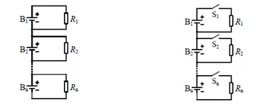
1. Passive Balance
Since the battery pack is discharged through the resistance all the time and released in the form of thermal energy, this virtually increases the burden on the thermal management system of the lithium battery. This kind of circuit is mainly used for battery packs with low capacity.
The balancing circuit adds a controllable switch to the fixed shunt resistance, and only discharges the battery with high power. Generally, the shunt resistance is adjusted so that the maximum balancing current is limited within 100mA. The vast majority of electric vehicles such as Tesla use this kind of balanced management.
The disadvantage of this circuit architecture is that it is essentially a dissipative equalizing circuit, the energy is not reused, and the equalizing current cannot be very large. The advantages are simple structure, reliability and low cost.
2. Active Balance
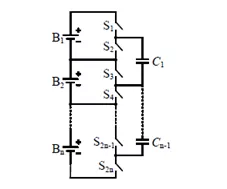
Active equalization circuits achieve equalization by redistributing energy between cells. According to the way of energy transfer, it can be divided into capacitive type, inductive type, transformer type, DC-DC converter type and multi-level converter type.
Assuming that battery B1 and battery B2 have different power levels, and the power level of B1 is higher than that of B2, balance the two cells, switch tubes S1 and S3 are turned on, S2 and S4 are turned off, and B1 transfers the power to the energy storage capacitor C1; then S2 and S4 are turned on, S1 and S3 are turned off, B2 is connected to C1, and the capacitor charges B2. In this way, the balance of the two batteries can be achieved.
The advantage of this architecture is that the energy is utilized through conversion, and the recovery rate is extremely high. The disadvantage is that the architecture is complex and the cost is high.
E: What characteristics should the best BMS in the world have?
First of all, in addition to the most basic functions mentioned above, secondly, a signal acquisition system with high accuracy and high stability is required, and finally, the software is the most complicated place.
The top BMS can estimate the battery parameters of the battery pack in real time online to accurately estimate the SOC, SOP, and SOH of the battery pack, and can correct the error of more than 10% of the initial SOC and the error of more than 20% of the ampere-hour capacity in a short time or Current measurement error of a few percent.
General Motors of the United States did an experiment to test the error correction ability of the algorithm when it developed Volanda 6 years ago: remove one battery pack with 3 series connected in parallel, then the internal resistance increases by 1/3, and the amp The capacity is reduced by 1/3. But BMS doesn't know that. The result is that SOC, SOP are all corrected in less than 1 minute and SOH is then accurately estimated. This not only shows the strong error correction ability of the algorithm, but also shows that the algorithm can keep the estimation accuracy unchanged throughout the life cycle of the battery.
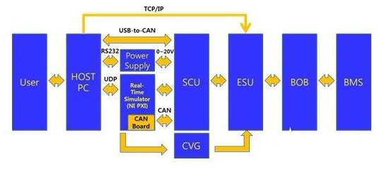
Figure: Communication process between BMS and system
For computers, if a blue screen appears, we generally only need to restart the computer. However, for a car, even if the probability of breaking down is only 1 in 10,000, it is intolerable. So, unlike published articles, automotive electronics need to be guaranteed to work under all circumstances.
Doing a good algorithm requires a lot of energy to solve those situations where the probability of occurrence is only 1 in 1,000 or 1 in 10,000. Only in this way can you guarantee nothing. The exact mathematical model is the textbook diffusion equation. But it cannot be used in cars because the numerical solution is too computationally intensive. The CPU computing power of the BMS is insufficient. This is not only an engineering problem, but also a mathematical and physical problem. Solving such technical difficulties can resolve almost all known polarization problems that affect battery state estimation.
Conclusion: State estimation is the core of BMS technology
Although there are many options for the principle, scheme, architecture, etc. of BMS, and the functions are different, the essence is to ensure that the lithium battery pack can work well and is foolproof.
Even Tesla cannot be perfect at present. Tesla's BMS can perform most functions well, but the accuracy and error correction ability of its algorithm cannot be guaranteed after the battery is aged. Otherwise, why would there be so many Tesla cars in need of emergency rescue?
How to correctly choose the correct BMS for the lithium battery pack?
Now that we understand the definition, function, classification, and core of BMS, the next step is to consider configuring a suitable BMS for expensive lithium battery packs.
We must first confirm one thing, that is, BMS is a highly customized thing, and it can be said that there are almost no functions that it cannot achieve, but R&D costs and manufacturing costs will vary greatly due to different requirements.
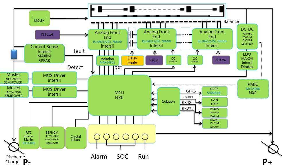
Figure: Demonstration of the electronic architecture of the BMS
SES Power has nearly 20 years of experience in the development and production of customized lithium battery packs, and is naturally very familiar with BMS. We recommend that you choose BMS according to the following steps:
A: Do you really need BMS or PCM?
In the case of realization, engineers of SES Power are often asked by customers about the difference between the two. In short, the full name of BMS is XXXXXXXX, which is a comprehensive lithium battery management system with software functions; the full name of PCM is XXXXXXXXX , it does not have software functions, but only has the most basic hardware detection and protection functions.
Most of the lithium battery packs that do not need communication functions use PCM because its functions are sufficient to meet the needs and the cost is low. For lithium battery packs that require communication functions and require complex functions, only BMS can be selected.
B: Inform the engineers of SES Power with clear parameters and requirements
These parameters include the hardware parameters of the lithium battery pack (nominal voltage, nominal capacity, maximum continuous current, maximum peak current, etc.), use environment, matched products (energy storage system, motor, lighting, etc.), charging conditions, etc.
Does the lithium battery pack need software communication, what kind of communication protocol (SMBus, RS485, CAN, Bluetooth, Wifi, TCP/IP, etc.), and whether the content of the communication protocol is customized or conforms to the general content of the industry?
The more detailed the parameters you provide, the more accurately SES Power can select the appropriate BMS for you.
C: Communicate frequently with engineers to determine details
There are many types and architectures of BMS, and the complexity and cost will vary greatly. Note that our topic is to choose a suitable BMS, not the most comprehensive and expensive BMS.
After you provide the comprehensive parameters to the engineers of SES Power, even if the engineers are full of experience, the engineers cannot have the upper computer of the lithium battery pack, that is, the equipment that will use the lithium battery pack in the future. Therefore, it is necessary to communicate with engineers even during the design process.
D: Choose the right components
In the process of detailed communication with engineers, how to use this lithium battery is also a very important part. For example, SES Power's 12V lead-acid replacement product, we consider that customers will use it in series, so we use 80V withstand voltage MOS. If it is an outdoor environment, the temperature resistance requirements of BMS will be much higher than those used indoors. Products with high temperature resistance should be selected for capacitors and resistors.
Conclusion: SES Power believes that BMS is actually a customized product, so communication is the first important thing, there is no best BMS, only the most suitable BMS.
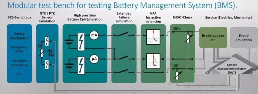
How to test the function of BMS?
BMS has a lot of functions, and the test process is also very complicated. SES Power will explain the test process and content of BMS in detail based on its own experience.
A: Limit test at the stage of research and development
We must make it clear that the limit test of any electronic product or equipment will damage the finished product, so these limit function tests are generally arranged in the research and development stage.
A1: Limit current and voltage shock
The purpose of this test is to determine the maximum current and voltage surge that the BMS can withstand, and whether it can meet the customer's extreme demands.
A2: Extreme temperature test
The purpose of this test is to determine whether the BMS can function properly within the ambient temperature limits proposed by the customer.
A3: ESD electrostatic test
There are many highly integrated ICs in the BMS. The purpose of this test is to determine whether the BMS can meet the requirements of anti-static.
A4: EMI/EMC testing
Lithium battery pack with BMS is actually an accessory. It is often used in many devices or systems with complex electromagnetic environment. The purpose of this test is to determine whether BMS can work in complex electromagnetic interference environment.
A5: FTA test
FTA (Failure Test Analysis), the purpose of this test is to clarify the state of the BMS in the event of failure of different components or accessories.
A6: Actual configuration limit test
These tests are matched with lithium battery packs, and then under different extreme conditions, test whether the BMS monitoring and management functions of lithium battery packs can maintain sufficient accuracy and reliability.
B: BMS test content in mass production stage
After the BMS design is finalized and passes the Class A test, it will enter the mass production stage. In the mass production stage, SES Power will generally conduct the following tests:
Description of the process | 1) BMS: Battery Management System; 2) The meaning of BMS: electrical adjustment + electrical safety management to solve the difference caused by the physical characteristics of the battery module; 3) The specific role of the electrical aspects of the BMS: A: Battery information monitoring and recording: voltage, current, temperature, communication, insulation, SOC, charge and discharge status, abnormal data; B: Battery control: balance adjustment, heat treatment, alarm, protection; 4) Test items: |
ITEMS | STEPS | CRITERIA | DEVICES |
1) Voltage detection | BMS tests the single cell voltage of each cell in the case of power failure, and then tests the total voltage of the battery pack, and records the results. After the BMS is powered on, compare the results of the two tests through the monitoring software of the BMS | Single cell voltage≤±1%, total voltage≤±1% | Six and a half digit multi-meter |
2) Current Detection | Connect the test equipment and the BMS under test. Charging test: 1) 0.2C (≤30A) charge for 1min, sleep for 1min; 2) 1C (>30A) charge for 1min, sleep for 1min. Discharge test: 1) 0.2C (≤30A) charge for 1min, sleep for 1min; 2) 1C (>30A) discharge for 1min, stop. | 3)I≤30A(precision <±0.3A)
4)I≤30A(precision <±1A) | Test equipment to simulate charging and discharging Oscilloscope with recording function |
3) Temperature test | Measure the actual problem and the problem reflected by BMS at 0℃, 25℃, 50℃ respectively | ≤±1℃ | Thermostat, temperature tester |
4) Insulation resistance test | 1) Insulation resistance between BMS system and vehicle chassis; 2) Apply 50-60hz positive sine wave AC, the voltage is 2U+1000V, after 1min (U is the rated voltage of the battery system) | >1MΩ | Megger |
5) Thermal management | Put the BMS and battery pack into the thermostat according to the design specifications, and adjust the problem to see if the fan is turned on/off at the specified temperature | Design Specs setting on or off | Thermostat |
6) State of charge (SoC) | The actual SOC of the battery pack is compared with the SOC data recorded by the BMS | 1)≤6%(SOC≥80%) 2)≤10%(80%>SOC>30%) 3)≤6%(SOC≤30%) | BMS Tester |
7) Cumulative battery discharge times | Cumulative charge and discharge times | According to design specifications | BMS Tester |
8) Balance function | Ability to adjust when the voltages of the cells are inconsistent | According to design specifications | BMS Tester |
9) Communication detection with in-vehicle equipment | After the installation is complete, check whether the in-vehicle devices can communicate normally | normal communication | BMS Tester |
10) Battery fault diagnosis and online alarm | Single cell temperature < set value | According to design specifications, alarm immediately after exceeding | BMS Tester |
Single cell temperature > set value | According to design specifications, alarm immediately after exceeding | BMS Tester |
Single cell voltage > set value | According to design specifications, alarm immediately after exceeding | BMS Tester |
Single cell voltage < set value | According to design specifications, alarm immediately after exceeding | BMS Tester |
Single cell voltage consistency deviation > set value | According to design specifications, alarm immediately after exceeding | BMS Tester |
Total voltage > set value | According to design specifications, alarm immediately after exceeding | BMS Tester |
Total voltage < set value | According to design specifications, alarm immediately after exceeding | BMS Tester |
Charge current > set value | According to design specifications, alarm immediately after exceeding | BMS Tester |
Discharge current > set value | According to design specifications, alarm immediately after exceeding | BMS Tester |
Communication interface failure | Analog fault alarm | BMS Tester |
11)Charging & Discharging test | Overvoltage protection: Charge the battery cells, causing a cell to be higher than the set value. After a period of time, observe whether the BMS does not allow to continue charging, so as to achieve protection | According to design specifications, protection immediately after exceeding | BMS Tester |
Over-discharge protection: the battery continues to discharge, when it exceeds the set value for a period of time, observe whether the BMS is not allowed to continue to discharge | According to design specifications, protection immediately after exceeding | BMS Tester |
Overheating: increase the temperature of the battery cell, the BMS hardware responds in a short time, and close the DC power circuit | According to design specifications, protection immediately after exceeding | BMS Tester |
The temperature is too low: reduce the temperature of the battery cell, the BMS hardware will respond in a short time, and the DC power circuit will be closed. | According to design specifications, protection immediately after exceeding | BMS Tester |
Overcurrent protection: the current higher than the set value is charged, and the response of the BMS will be seen in a short time, whether charging is not allowed; | According to design specifications, protection immediately after exceeding | BMS Tester |
Charging indication: Discharge until the SOC of the battery pack is too low, observe whether the BMS gives a mark requiring charging, and control whether the LED indication of charging is turned on. Whether to show the full mark when full. | According to design specifications, protection immediately after exceeding | BMS Tester |
12) Running data logging | After running for a while, look at the log file. and verify the authenticity of the data | match the actual operation | BMS Tester |
Analysis method and treatment method after BMS failure
Although the lithium-ion battery pack is assembled after the BMS has undergone rigorous testing, some failures will still occur during the operation. The following is the analysis method and case analysis provided by the senior engineers of SES Power for you.
A: BMS failure analysis method
A1 observation method
When the communication is interrupted or the control is abnormal in the system, observe whether each module of the system has an alarm, whether there is an alarm icon on the display screen, and then check the obtained phenomena one by one.
A2 fault reproduction method
The failures of lithium battery packs under different conditions are different. If conditions permit, the failures should be reproduced under the same conditions as much as possible, and the problem points should be confirmed.
A3 Exclusion
When a similar interference phenomenon occurs in the BMS system, each component in the system should be removed one by one to determine which part affects the system.
A4 replacement method
When a module is abnormal in temperature, voltage, control, etc., replace the module positions with the same number of strings to diagnose the module problem or the wiring harness problem.
A5 Environmental Inspection Act
When the system fails, we should not rush into in-depth consideration, because often we ignore some details. First we should look at the obvious: if so is it plugged in? Is the switch turned on? Are all wiring connected? Perhaps the root of the problem lies in it.
A6 program upgrade method
When an unknown fault occurs after the new program is programmed, resulting in abnormal system control, the previous version of the program can be programmed for comparison to analyze and deal with the fault.
A7 Data Analysis
When a control or related fault occurs in the BMS, the data stored in the BMS can be analyzed, and the content of the messages in the CAN bus can be analyzed.
B: Analysis of 15 common failure cases
B1. The whole system does not work after the system is powered on
Possible reasons: abnormal power supply, short circuit or open circuit of wiring harness, no voltage output of DCDC
Treatment method: Check whether the external power supply supplies power to the management system normally, whether it can reach the minimum operating voltage required by the management system, and see if the external power supply is limited in current setting, resulting in insufficient power supply to the management system;
The external power supply can be adjusted to meet the power requirements of the management system; check whether the wiring harness of the management system is short-circuited or open, and modify the wiring harness to make it work normally; if the external power supply and wiring harness are normal, check the power supply in the management system. Check whether the DCDC powered by the whole system has voltage output; if there is any abnormality, replace the bad DCDC module.
B2. BMS cannot communicate with ECU
Possible reasons: BMU (main control module) is not working, CAN signal line is disconnected
Treatment method: Check whether the power supply of the BMU is normal at 12V/24V; check whether the CAN signal transmission line is withdrawn or the plug is not inserted; monitor the CAN port data to see if it can receive BMS or ECU data packets.
B3. The communication between BMS and ECU is unstable
Possible reasons: The external CAN bus is poorly matched, and the bus branch is too long
Solution: Troubleshooting Check whether the bus matching resistance is correct; whether the matching position is correct, and whether the branch is too long.
B4, BMS internal communication is unstable
Possible reasons: The plug of the communication cable is loose, the CAN wiring is not standardized, and the BSU address is duplicated.
Treatment method: check whether the wiring is loose; check whether the bus matching resistance is correct, whether the matching position is correct, and whether the branch is too long; check whether the BSU address is repeated.
B5. Insulation detection alarm
Possible reasons: battery or driver leakage, wrong connection of insulation module detection line.
Treatment method: Use the host computer software to check the insulation test data, check the voltage of the battery bus, and whether the voltage of the negative bus to ground is normal; use an insulation shaker to measure the insulation resistance of the bus and the driver to ground respectively.
B6. The main relay does not pull in after power-on
Possible reasons: The load detection line is not connected, the precharge relay is open, and the precharge resistor is open.
Treatment method: Use the BDU display module or the host computer software to check the bus voltage data, observe the battery bus voltage, and whether the load bus voltage is normal; check whether the load bus voltage rises during the precharging process.
B7, the acquisition module data is 0
Possible reasons: The acquisition line of the acquisition module is disconnected, and the acquisition module is damaged.
Treatment method: re-plug the module wiring, measure whether the battery voltage is normal at the connector of the collection line, and measure whether the resistance value is normal at the plug of the temperature sensor line.
B8, battery current data error
Possible reasons: The plug of the Hall signal line is loose, the Hall sensor is damaged, and the acquisition module is damaged.
Treatment method: re-plug the current Hall sensor signal line; check whether the Hall sensor power supply is normal and whether the signal output is normal; replace the acquisition module.
B9, the battery temperature difference is too large
Possible reasons: The cooling fan plug is loose, and the cooling fan is faulty.
Solution: re-plug the fan plug; supply power to the fan alone, and check whether the fan is normal.
B10, the battery temperature is too high or too low
Possible reasons: The cooling fan plug is loose, the cooling fan is faulty, and the temperature probe is damaged.
Treatment method: re-plug the fan plug cable; supply power to the fan alone, check whether the fan is normal; check whether the actual temperature of the battery is too high or too low; measure the internal resistance of the temperature probe.
B11. The system reports an error after the relay operates
Possible reasons: relay auxiliary contact disconnection, relay contact sticking
Treatment method: re-plug the wiring harness; use a multimeter to measure whether the on-off state of the auxiliary contact is correct.
B12, can not be charged normally
Possible reasons: BMS communication is abnormal or data error
Solution: Replace the charger or BMS to confirm whether it is the BMS fault or the charger fault; check whether the matching resistance and data content of the BMS charging port are normal.
B13. The detection data of some battery boxes is lost
Possible reasons: Some connectors of the system may be in poor contact, or the BMS slave control module may not work properly
Treatment method: Check the contact of the connector, or replace the BMS module.
B14. SOC abnormal phenomenon: SOC changes greatly during system operation, or jumps repeatedly between several values; during system charging and discharging, SOC has a large deviation; SOC always shows a fixed value.
Possible reasons: the current is not calibrated; the current sensor model does not match the host program; the battery has not been deeply charged and discharged for a long time; the data acquisition module jumps in acquisition, causing the SOC to automatically calibrate; two conditions for SOC calibration: 1) Overcharge protection is achieved; 2) The average voltage is above the set voltage value. The customer's battery has poor consistency, and the second condition cannot be reached when it is overcharged. Check the remaining capacity and total capacity of the battery through the display; the current sensor is not connected properly;
Processing method: re-calibrate the current; change the host program or replace the current sensor; perform a deep charge and discharge on the battery; replace the data acquisition module, and manually calibrate the system SOC. It is recommended that the customer do a deep charge and discharge once a week; According to the actual situation of the customer, adjust xxV in the condition of "average voltage reaches xxV or more". Set the correct total battery capacity and remaining capacity; connect the current sensor correctly to make it work properly;
B15, BSU voltage acquisition is not allowed
Possible cause: The battery pack is not calibrated after PACK
Treatment method: re-calibrate, and check whether the wiring harness has poor contact when the error is large.
The above is the analysis and handling of common BMS faults. If you have more questions, please contact SES Power, and we will explain and deal with it from a professional perspective.