The editor summarizes some common methods when dealing with battery
management system failures and case analysis of common failures of battery
management system, for reference by relevant personnel of vehicle, battery, and
management system manufacturers.
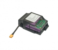
The battery management system (BATTERYMANAGEMENTSYSTEM), commonly known as
battery nanny or battery housekeeper, is an important link between on-board
power batteries and electric vehicles. Its main functions include: real-time
monitoring of battery physical parameters; battery state estimation; online
diagnosis and early warning; charging, discharging and Pre-charge control;
balance management and thermal management, etc. The battery management system
(BMS) is mainly to improve the utilization of the battery, prevent the battery
from overcharging and overdischarging, prolong the service life of the battery,
and monitor the status of the battery.
The battery management system is not only closely related to the battery,
but also has various connections with the vehicle system. Among all the faults,
the battery management system is relatively high compared to other systems, and
it is also more difficult to deal with. The editor summarizes some common
methods when dealing with battery management system failures and case analysis
of common failures of battery management system, for reference by relevant
personnel of vehicle, battery, and management system manufacturers.
BMS failure analysis method
Observation
When the system has a communication interruption or a control abnormality,
observe whether each module of the system has an alarm and whether there is an
alarm icon on the display screen, and then check the phenomenon one by one.
failure reproduction method
The failures of vehicles under different conditions are different. If
conditions permit, try to reproduce the failures under the same conditions as
much as possible to confirm the problem.
Exclusion
When similar interference occurs in the system, each component in the
system should be removed one by one to determine which part is affecting the
system.
substitution method
When a certain module has abnormalities in temperature, voltage, control,
etc., change the position of the module with the same number of strings to
diagnose the module problem or the wiring harness problem.
Environmental Inspection Law
When the system fails, such as the system cannot be displayed, we should
not rush to carry out in-depth consideration, because often we will ignore some
details. First of all we should look at the obvious things: if it is plugged in?
Is the switch turned on? Are all the wires connected? Perhaps the root of the
problem lies in it.
program upgrade method
When an unknown fault occurs after the new program is burned, which results
in abnormal system control, the previous version of the program can be burned
for comparison to analyze and deal with the fault.
data analysis method
When a control or related failure occurs in the BMS, the BMS stored data
can be analyzed, and the message content in the CAN bus can be analyzed.
Common failure case analysis
1. The whole system does not work after the system is powered
Possible Causes
The power supply is abnormal, the wiring harness is short-circuited or
disconnected, and the DCDC has no voltage output.
Troubleshooting
Check whether the external power supply to the management system is normal,
whether it can reach the minimum operating voltage required by the management
system, and whether the external power supply is set to limit current, resulting
in insufficient power supply to the management system; the external power supply
can be adjusted to meet the requirements of the management system Electricity
requirements; check whether the harness of the management system is
short-circuited or open, modify the harness to make it work normally; if the
external power supply and harness are normal, check whether the DCDC powering
the entire system in the management system has a voltage output; if so If
abnormal, the bad DCDC module can be replaced.
2, BMS cannot communicate with ECU
Possible Causes
BMU (main control module) is not working, CAN signal line is
disconnected
Troubleshooting
Check whether the 12V/24V power supply of the BMU is normal; check whether
the CAN signal transmission line is withdrawn or the plug is not plugged in;
monitor the CAN port data and whether the BMS or ECU data packet can be
received.
3, BMS and ECU communication is unstable
Possible Causes
The external CAN bus is poorly matched, and the bus branch is too long
Troubleshooting
Check whether the bus matching resistance is correct; whether the matching
position is correct and whether the branch is too long.
4, BMS internal communication is unstable
Possible Causes
The communication line plug is loose, the CAN wiring is not standardized,
and the BSU address is duplicated.
Troubleshooting
Check whether the wiring is loose; check whether the bus matching
resistance is correct, whether the matching position is correct, and whether the
branch is too long; check whether the BSU address is duplicated.
5, insulation detection alarm
Possible Causes
Leakage of battery or drive. , The detection line of the insulation module
is connected incorrectly.
Troubleshooting
Use the BDU display module to check the insulation test data, check the
battery bus voltage, whether the negative bus voltage to ground is normal; use
the insulation shaker to measure the insulation resistance of the bus and the
driver to the ground.
6. The main relay does not close after power-on
Possible Causes
The load detection line is not connected, the pre-charge relay is open, and
the pre-charge resistor is open.
Troubleshooting
Use the BDU display module to check the bus voltage data, check the battery
bus voltage, whether the load bus voltage is normal; check whether the load bus
voltage rises during the pre-charging process.
7, the acquisition module data is 0
Possible Causes
The collection line of the collection module is disconnected, and the
collection module is damaged.
Troubleshooting
Re-plug the module wiring, measure whether the battery voltage is normal at
the collection line connector, and measure the resistance at the temperature
sensor line plug.
8. Battery current data error
Possible Causes
The Hall signal cable plug is loose, the Hall sensor is damaged, and the
acquisition module is damaged.
Troubleshooting
Re-plug and plug the signal wire of the current Hall sensor; check whether
the power supply of the Hall sensor is normal and whether the signal output is
normal; replace the acquisition module.
9, the battery temperature difference is too large
Possible Causes
The cooling fan plug is loose, and the cooling fan is faulty.
Troubleshooting
Reconnect the fan plug wire; power the fan separately and check whether the
fan is normal.
10, the battery temperature is too high or too low
Possible Causes
The cooling fan plug is loose, the cooling fan is faulty, and the
temperature probe is damaged.
Troubleshooting
Re-plug the fan plug; power the fan separately and check whether the fan is
normal; check whether the actual temperature of the battery is too high or too
low; measure the internal resistance of the temperature probe.
11, the system reports an error after the relay operates
Possible Causes
Relay auxiliary contacts are broken, and relay contacts are sticking
Troubleshooting
Re-plug the wiring harness; use a multimeter to measure whether the
auxiliary contact is on or off correctly.
12. Cannot use charger to charge
Possible Causes
The communication between the charger and the BMS is abnormal
Troubleshooting
Replace a charger or BMS to confirm whether the BMS is faulty or the
charger is faulty; check whether the matching resistance of the BMS charging
port is normal.
13. There is no BMS data display on the vehicle instrument
Possible Causes
The main control module wiring harness connection is abnormal
Troubleshooting
Check whether the main control module wiring harness is fully connected,
whether there is a normal low-voltage working voltage for the car, and whether
the module is working properly
14. The detection data of some battery boxes is lost
Possible Causes
Some connectors of the whole vehicle may be in poor contact, or the BMS
slave control module may not work normally
Troubleshooting
Check the contact of the connector, or replace the BMS module;.
15, SOC abnormal
Phenomenon: SOC changes greatly during the working process of the system,
or repeatedly jumps between several values; during the charging and discharging
process of the system, the SOC has a large deviation; the SOC always shows a
fixed value.
Possible Causes
The current is not calibrated; the current sensor model does not match the
host program; the battery has not been deeply charged and discharged for a long
time; the data acquisition module acquisition jumps, which causes the SOC to be
automatically calibrated;
Two conditions for SOC calibration: 1) Reach overcharge protection; 2) The
average voltage reaches xxV or more. Customer battery consistency is poor, and
the second condition cannot be met when overcharged. Check the remaining
capacity and total capacity of the battery through the display; the current
sensor is not connected correctly;