About Li-ion battery linear charging solution
This article discusses the use of high-current lithium-ion battery charging
chip SE9018 to design a linear charging scheme for lithium-ion batteries.
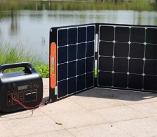
With the development of modern electronic technology, electronic devices
are becoming more portable and multifunctional, so their power supply batteries
are also required to be portable and efficient. Lithium-ion batteries are
gradually replacing traditional nickel-cadmium, nickel-hydrogen batteries, and
lead-acid batteries with their high energy density, excellent charge and
discharge performance, and pollution-free characteristics, and are widely used
in modern portable electronic products. Compared with other types of batteries,
lithium-ion batteries have excellent performance and higher requirements for
chargers. These requirements are mainly reflected in the control of the charging
process and the protection of lithium batteries. The specific performance is
large charging current and high charging current. Accurate charging voltage,
staged charging mode and complete protection circuit, etc. This article
discusses the use of high-current lithium-ion battery charging chip SE9018 to
design a linear charging scheme for lithium-ion batteries. Chip
introduction SE9018 is a linear charging chip for lithium-ion batteries in
constant current/constant voltage mode. It uses an internal PMOSFET architecture
and integrates an anti-reverse charging circuit without external isolation
diodes. The preset charging voltage of the chip is 4.2V, the accuracy is ±1.5%,
the charging current can be set by an external resistor, and the maximum
continuous charging current can reach 1A. When the junction temperature of the
chip is higher than 140°C due to high working power, high ambient temperature or
poor PCB heat dissipation, the internal thermal feedback circuit will
automatically reduce the charging current to keep the chip temperature within a
safe range. In order to keep the chip working efficiently, measures should be
taken to reduce the chip's working power and chip temperature as much as
possible, such as connecting a small resistor in series at the input (reducing
the input voltage), increasing the area of the PCB heat dissipation copper
foil, and making the chip heat sink and PCB copper foil sufficient Contact
etc.
Figure 1SE9018 pin map
Figure 2SE9018 schematic
SE9018 integrates a battery temperature monitoring circuit. When the
battery temperature exceeds the normal range (too high or too low), the chip
automatically stops the charging process to prevent the battery from being
damaged due to the high or low temperature. Battery temperature monitoring is
achieved by judging the TEMP terminal voltage (VTEMP). VTEMP is provided by a
resistor divider network including the internal NTC thermistor of the battery.
When VTEMP is between 45%×VCC and 80%×VCC, the chip judges that the battery
temperature is within the normal range; when VTEMP<45%×VCC or
VTEMP>80%×VCC, the chip judges that the battery temperature is too high or
too low ; When the TEMP terminal is grounded, the battery temperature monitoring
function is disabled. SE9018 contains two open-drain status indicating output
terminals CHRG and STDBY. When the circuit is in the charging state, the CHRG
terminal is set to low level, and the STDBY terminal is in a high impedance
state; when the battery is fully charged, the CHRG terminal becomes a high
impedance state , STDBY terminal is set to low level. When the battery
temperature monitoring function is used normally, if the chip is not connected
to the battery or the battery temperature is out of the normal range, the CHRG
terminal and STDBY terminal are both high impedance; when the battery
temperature monitoring function is disabled, if the chip is not connected to the
battery, the STDBY terminal is Low level, the CHRG terminal outputs a pulse
signal. SE9018's other functions include manual shutdown, undervoltage
lockout, automatic recharging, etc. A typical SE9018-based lithium-ion battery
charging circuit is shown in Figure 3. When the CE terminal is high, the SE9018
works normally. Smart high-current lithium-ion battery linear charging
scheme
Figure 3SE9018 typical application circuit 1. Setting of charging current
The charging current Ibat during constant current charging is set by the
resistance Rprog between PORG and GND. The relationship between Ibat and Rprog
is:
Formula 1 For example, if you want to get a constant charging current of
1A, according to formula 1, you can get Rprog=1200Ω. 2. Battery temperature
monitoring circuit settings The battery temperature monitoring circuit settings
are mainly to set R1 and R2, assuming that the resistance of the NTC thermistor
at the lowest operating temperature is RTL, and the resistance at the highest
operating temperature is RTH (RTL and RTH The data can be found in the relevant
battery manual or obtained through experiments), then the resistance values of
R1 and R2 are:
formula 2
formula 3
In practical applications, if only high temperature protection is needed,
but low temperature protection is not required, R2 can be removed. At this time,
the resistance of R1 is:
Formula 4 3. Manual shutdown setting During the charging process, SE9018
can be placed in shutdown state by setting CE terminal to low level or removing
Rprog (PROG terminal floating) at any time. At this time, battery leakage
current drops below 2uA, input current Reduced to below 70uA. 4. Undervoltage
lockout status If the input voltage VCC is lower than the undervoltage lockout
threshold or the difference between VCC and the battery voltage Vbat is less
than 120mV, the SE9018 is in the undervoltage lockout state. When the chip is
in shutdown state or under-voltage lockout state, both CHRG and STDBY are in
high impedance state. 5. Normal charging cycle. When the input terminals of
SE9018 and the battery are in the normal state, the charging circuit enters the
normal charging cycle. This cycle includes four basic working modes: trickle
charging, constant current charging, constant voltage charging, and charging end
And recharge. If the battery voltage Vbat is lower than 2.9V, the charging
circuit enters trickle charging mode, at this time the charging current is
one-tenth of the constant current charging current (if the constant current
charging current is set to 1A, the trickle charging current is 100mA) , The
trickle charge state will be maintained until the battery voltage Vbat reaches
2.9V. The trickle charging mode is mainly to avoid the damage to the internal
structure of the battery caused by the high current impact when the battery
voltage is too low. When the battery voltage is higher than 2.9V but lower
than the preset full charge voltage of 4.2V, the charging circuit is in constant
current charging mode. As mentioned above, the charging current is determined by
Rprog. When the battery voltage reaches 4.2V, the charging circuit enters the
constant voltage charging mode. At this time, the BAT terminal voltage is
maintained at 4.2V, and the charging current gradually decreases. The main
function of this process is to reduce the impact of the battery's internal
resistance on the full-charge voltage and make the battery more fully
charged.