-
- Lithium Ion Cell
>
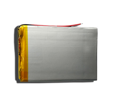
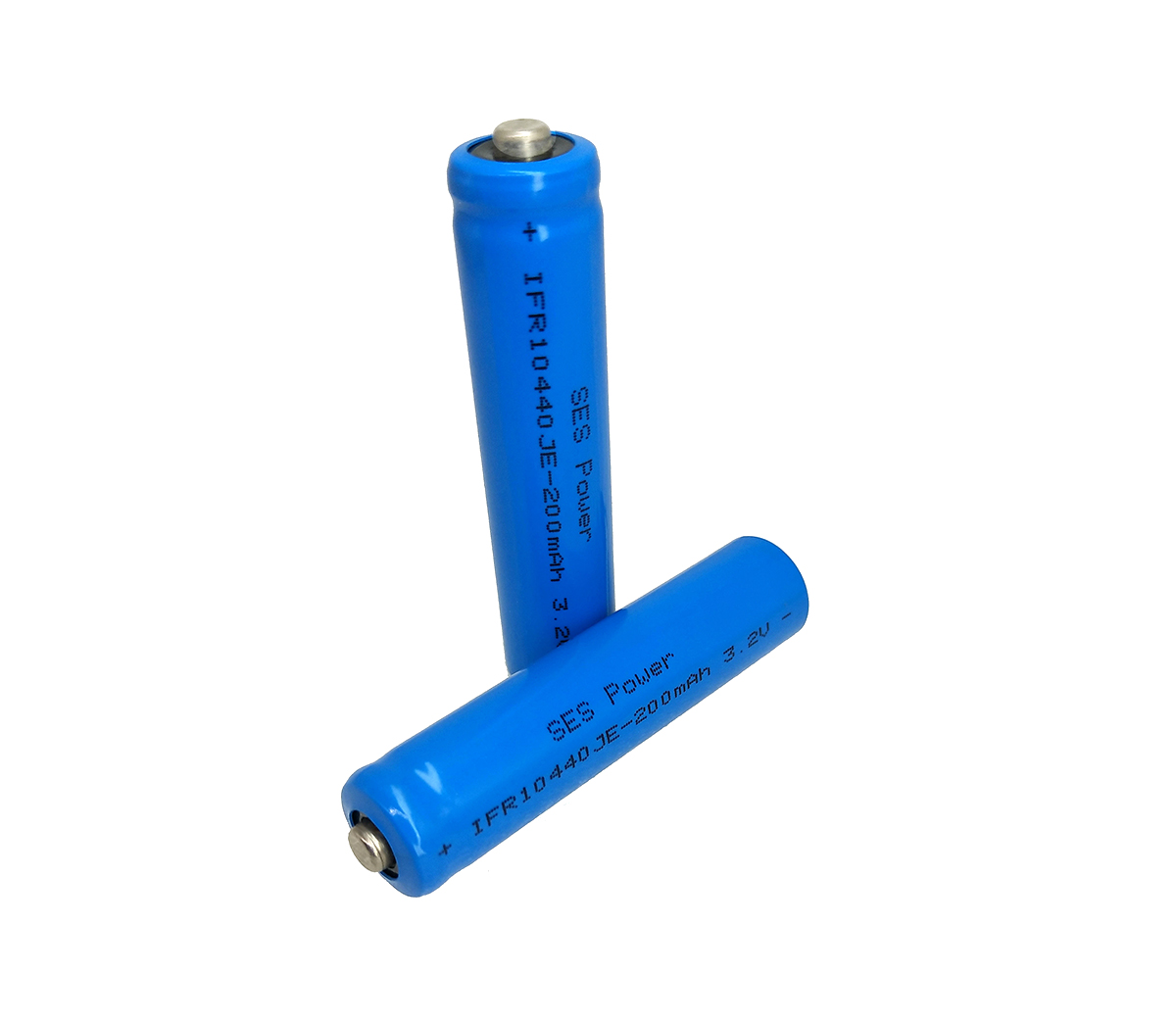
- 3.2V LiFePo4 Cylindrical Cell 3.2V LiFePo4 Aluminum Shell Cell 3.7V Li Ion Cylindrical Cell 3.2V LiFePo4 Polymer Cell Special Cell
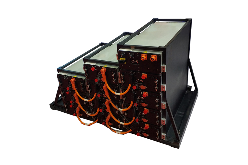
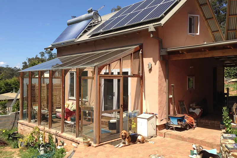
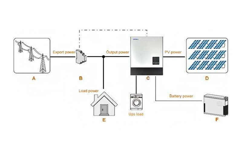
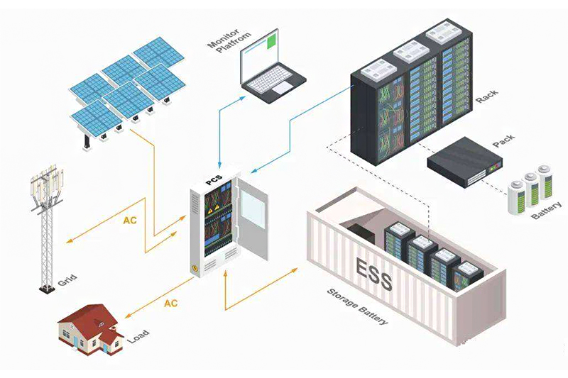
- Energy Storage System
>
- Telecom Base Battery Household ESS Off-grid ESS On-grid ESS Micro-grid System Outdoor Mobile ESS
- Standard Lead-Acid Replacement Battery
>
- 12V Series 24V Series 36V Series 48V Series 12V Series with Communication 24V Series with Communication 36V Series with Communication 48V Series with Communication
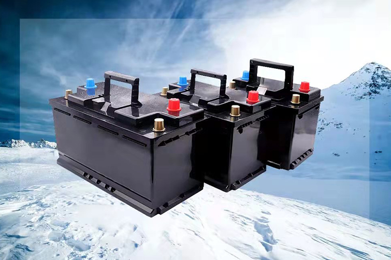
- Low Temperature Lead-Acid Replacement Battery
>
- Low Temp. 12V Series Low Temp. 24V Series Low Temp. 36V Series Low Temp. 48V Series Low Temp. 12V Series with Communication Low Temp. 24V Series with Communication Low Temp. 36V Series with Communication Low Temp. 48V Series with Communication
- Starting Lead-Acid Replacement Battery
>
- Automotive Starting Battery Generator Starting Battery Motor Starting Battery High Rate 12V~48V Series High Rate 12V~48V Series with Communication
- E-Mobility Battery
>
- Golf Car Battery E-Car Battery E-Bike Battery E-Boat Battery AGV Battery E-Forklift Battery
- Industrial Battery
>
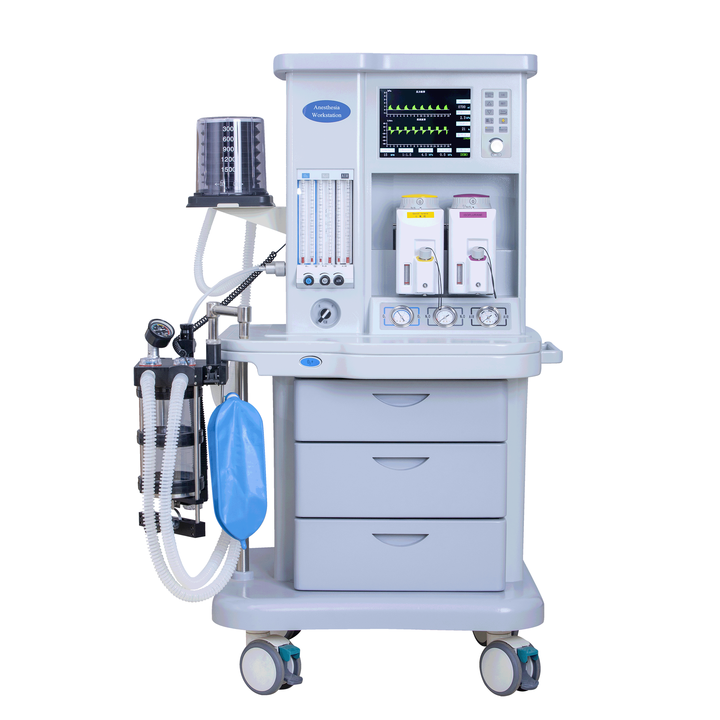
- Lawn Lamp Battery Solar Street Light Battery Medical Battery Marine Battery Equiment Battery Outdoor Low Temp. Battery UPS/Dc-Ac Battery
- Household Appliances Battery
>
- Protable Power Station Toys Battery Flashlight Battery Consumer Electronics Battery Other Battery
- Lithium Ion Cell
-
- Battery Guide
>
- Battery Basic Knowledges Battery glossary & Battery-Related Abbreviations How to Choose appropriate Lithium Ion Battery Guide Best Lithium Ion Battery Guide Best Lithium ion Battery Pack Guide Lithium Ion Battery Certification and Test Guide Best Li-Ion Battery Packing Method and Problem Solving Guide
- Do It Youself
>
- 12V lithium battery for replacing lead-acid is on a larger scale, Tesla, BMW, BYD have all accelerat American lithium battery the rise and fall of A123, only a sigh is left in the end
- FAQ
>
- Battery Guide