First of all, first of all, I need a circuit diagram of a 12v charger. Dad
said that if there is a diagram, it is easy to do it. According to the drawing,
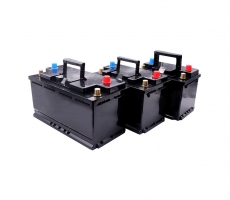
it can be clearly thought out and made quickly and easily. Homemade 12v
battery charger
First of all, first of all, I need a circuit diagram of a 12v charger. Dad
said that if there is a diagram, it can be done. According to the drawing, it
can be clearly thought out and made quickly and easily.
Homemade 12v battery charger
Prepare the materials you need. First, you need a 12V5-15A AC transformer,
a 6-10A high-power rectifier diode, a 25V2200uf capacitor tube, a low-voltage
power control switch, and a 220V power plug. Insulating tape 1 roll. In
addition, a rubber hose with a diameter larger than the diameter of the
high-power rectifier diode 0.3cm30-50cm is required (water-proof type, for
cooling the rectifier diode), and 1 plastic empty bottle (for cooling the
rectifier diode)
Homemade 12v battery charger
END
Method/Step 2
Connect the 220V power plug and the input end of the transformer with
wires, and wrap the connector with insulating tape. Because the AC power supply
has no positive and negative poles, so the input terminal is connected casually,
but the input terminal and output terminal must not be mistaken. There are
indications of input and output on the transformer, and you must see
clearly.
Homemade 12v battery charger
Connect both ends of the rectifier diode with wires of the same length, but
the total length should exceed the length of the 30-50cm rubber hose, and then
pass one end through the 30-50cm rubber hose so that the rectifier diode is in
the middle of the rubber hose .
Homemade 12v battery charger
Connect a wire from the 12V output end of the transformer to the positive
(or negative) end of the rectifier diode with a wire and wrap the connector with
insulating tape.
Homemade 12v battery charger
Connect the other line of the 12V output end of the transformer to the
positive (or negative) end of the capacitor tube, and connect the negative (or
positive) end to the negative (or positive) end of the rectifier diode with a
wire, and wrap the connector with insulating tape.
Homemade 12v battery charger
Then connect the positive and negative ends of the capacitor tube to the
wires (lead wire, that is, the wire at both ends of the battery), connect the
positive end to the low-voltage power control switch and connect the wire to the
negative end of the same length, and wrap the connector with insulating tape
That's it.
When the cell voltage is between 2.5V and 4.3V, the first pin and the third
pin of DW01 both output high level (equal to the supply voltage), and the second
pin voltage is 0V. At this time, the voltages of pin 1 and pin 3 of DW01 will be
applied to pins 5 and 4 of 8205A respectively. The two electronic switches in
8205A are in the conducting state because their G poles are connected to the
voltage from DW01. Both electronic switches are in the open state. At this time,
the negative pole of the battery is directly connected to the P- terminal of the
protection board, and the protection board has a voltage output.
12v lithium battery protection board circuit diagram
2, over-discharge protection control principle of the protection board
When the cell is discharged through an external load, the cell voltage will
slowly decrease, and the internal DW01 will monitor the cell voltage through the
R1 resistor in real time. When the cell voltage drops to about 2.3V, DW01 will
consider that the cell voltage has been In the over-discharge voltage state,
immediately disconnect the output voltage of the first pin, so that the voltage
of the first pin becomes 0V, and the switch tube in the 8205A is closed because
there is no voltage on the fifth pin. At this time, the B- of the battery cell
and the P- of the protection board are in a disconnected state. That is, the
discharge circuit of the battery cell is cut off, and the battery cell will stop
discharging. The protection board is in an over-discharge state and has been
maintained. After the P and P- of the protection board have indirect charging
voltages, DW01 will immediately stop the over-discharge state after B- detects
the charging voltage, and output a high voltage at pin 1 again to turn on the
over-discharge control tube in the 8205A. That is, the B- of the battery cell
and the P- of the protection board are reconnected, and the battery is directly
charged by the charger.
12v lithium battery protection board circuit diagram
3, protection board overcharge protection control principle
When the battery is normally charged by the charger, as the charging time
increases, the voltage of the cell will become higher and higher. When the cell
voltage rises to 4.4V, DW01 will consider the cell voltage to be in an
overcharge voltage state. It immediately disconnects the output voltage of the
third pin, so that the voltage of the third pin becomes 0V, and the switch tube
in the 8205A is closed because the fourth pin has no voltage. At this time, the
B- of the battery cell and the P- of the protection board are in a disconnected
state. That is, the charging circuit of the battery cell is cut off, and the
battery cell will stop charging. The protection board is in an overcharged state
and has been maintained. After the P and P- of the protection board discharge
the load indirectly, although the overcharge control switch is turned off, the
forward direction of the diode inside is the same as the direction of the
discharge circuit, so the discharge circuit can discharge. When the voltage of
the battery cell When the voltage is lower than 4.3V, DW01 stops the overcharge
protection state and outputs high voltage at pin 3 again, so that the overcharge
control tube in 8205A is turned on, that is, the B- of the battery and the
protection board P- are reconnected , The battery cell can be charged and
discharged normally.
4, protection board short-circuit protection control principle
In the process of external discharge of the protection board, the two
electronic switches in the 8205A are not completely equivalent to two mechanical
switches, but are equivalent to two resistors with very small resistances, and
are called the conduction internal resistance of the 8205A. The on-resistance of
each switch is about 30mU03a9 and a total of about 60mU03a9. The voltage applied
to the G pole actually directly controls the on-resistance of each switch. When
the G pole voltage is greater than 1V, the conduction of the switch The internal
resistance of the switch is very small (tens of milliohms), which is equivalent
to the switch being closed. When the voltage of the G pole is less than 0.7V,
the internal resistance of the switch tube is very large (several MΩ), which is
equivalent to the switch being disconnected. The voltage UA is the voltage
generated by the internal resistance of 8205A and the discharge current. When
the load current increases, UA will inevitably increase. Because
UA0.006L&TImes;IUA is also called the tube voltage drop of 8205A, UA can be
abbreviated to indicate the size of the discharge current. . When it rises to
0.2V, it is considered that the load current has reached the limit value, so the
output voltage of pin 1 is stopped, so that the voltage of pin 1 becomes 0V, the
discharge control tube in 8205A is closed, and the discharge circuit of the
battery is cut off. Discharge control tube. In other words, the maximum current
allowed by DW01 is 3.3A, which realizes over-current protection.