The application of the battery technology of portable electronic devices is
the basis for choosing lithium-ion batteries and lithium polymer batteries and
their chargers. The correct choice must also depend on the specific requirements
of the portable electronic devices.
1. Battery charging algorithms for trickle charging, fast charging and
stable charging
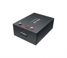
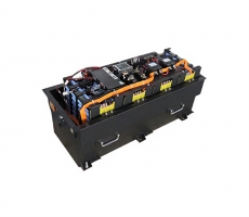
According to the energy requirements of the final application, a battery
pack may contain up to 4 lithium ion or lithium polymer battery cells, and its
configuration can be varied, and it also has a mainstream power adapter: direct
adapter, USB interface or car charging Device.
*Trick current charging. It is used to charge deeply discharged batteries.
When the cell voltage is lower than about 2.8V, a constant 0.1C current is used
to charge it.
*Fast charging. When the cell voltage exceeds the threshold of trickle
charging, increase the charging current for fast charging. The fast charge
current should be lower than 1.0C.
* Stable voltage. During the fast charging process, once the cell voltage
reaches 4.2V, the voltage stabilization phase begins. At this time, the charging
can be interrupted by the minimum charging current or the timer or the
combination of the two. When the minimum current is lower than about 0.07C, the
charging can be interrupted. The timer relies on a preset timer to trigger an
interrupt.
Advanced battery chargers usually come with additional safety features. For
example, if the cell temperature exceeds a given window, which is usually
0°C--45°C, charging will be suspended. Except for some very low-end devices, the
current lithium-ion/lithium-polymer battery charging solutions on the market are
integrated or have external components to charge according to the charging
characteristics. This is not only to achieve better charging results, It is also
for safety.
2, Li-ion/polymer battery charging scheme
Li-ion/polymer battery charging schemes are different for different numbers
of cells, cell configuration, and power source types. There are currently three
main charging schemes: linear, Buck (buck) switch and SEPIC (boost and buck)
switch.
2.1 Linear scheme
When the charger input voltage is greater than the open circuit voltage of
a fully charged cell plus sufficient headroom, it is best to use a linear
solution, especially when the 1.0C fast charging current is not too much larger
than 1A.
MAX8677A can work under independent USB and AC adapter power input or under
either input of two inputs. When connected to an external power source, the
smart power selector allows the system to be disconnected from a battery or can
be connected to a deeply discharged battery.
2.2Buck (buck) switch scheme
When the 1.0C charging current is greater than 1A, or the input voltage is
much higher than the fully charged open circuit voltage of the cell, Buck or a
step-down solution is a better choice. For example, in a hard disk-based PMP, a
single-cell lithium-ion battery is usually used, the open circuit voltage is
4.2V when fully charged, and the capacity ranges from 1200 to 2400mAh. Now PMP
is usually charged with a car kit, and its output voltage is between 9V and 16V.
The relatively high voltage difference (minimum 4.8V) between the input voltage
and the battery voltage will reduce the efficiency of the linear scheme. This
low efficiency, coupled with a 1C fast charging current greater than 1.2A, will
cause serious heat dissipation problems. In order to avoid this situation, it is
necessary to adopt the Buck scheme. Figure 3 is a schematic diagram of a
lithium-ion/polymer battery Buck charger scheme. The basic structure is exactly
the same as the Buck (buck) switching voltage regulator.
2.3SEPIC (boost and buck) switching scheme
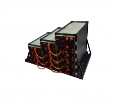
In some devices that use 3 or 4 lithium-ion/polymer cells in series, the
input voltage of the charger is not always greater than the battery voltage. For
example, a laptop computer uses a 3-cell lithium-ion battery pack with a fully
charged open circuit voltage of 12.6V (4.2Vx3) and a capacity from 1800mAh to
3600mAh. The input power supply is either an AC/DC adapter with an output
voltage of 16V or a car kit with an output voltage between 9V and 16V.
Obviously, neither linear nor Buck solutions can charge this battery pack. This
requires the use of the SEPIC solution, which can work when the output voltage
is higher than the battery voltage, and can also work when the output voltage is
lower than the battery.
3, power detection algorithm
Many portable products use voltage measurements to estimate the remaining
battery power, but the relationship between battery voltage and remaining power
will change with the discharge rate, temperature, and battery aging. This method
has the highest error rate. Up to 50%.
3.1 One of the application examples of the power detection algorithm, a
fully functional single/dual battery portable application battery pack
design
*The principle of power detection. A better power meter must at least have
battery voltage, battery temperature and current, measurement methods; a
microprocessor 9a; and a set of proven power detection algorithms. The bq2650x
and bq27x00 are fully functional fuel gauges with an analog-to-digital converter
(ADC) for measuring voltage and temperature and an analog-to-digital converter
for measuring current and charging sensing.
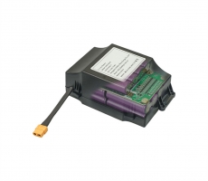
*Battery pack circuit description. Figure 4(a) is a typical battery pack
application circuit that can choose to use an IC with identification function.
Depending on the fuel gauge IC used, the battery pack needs at least three to
four external terminals. The VCC and BAT pins will be connected to the battery
voltage in order to supply power to C and measure the battery voltage.
3.2 The second example of the application of the power detection algorithm,
which can be applied to a variety of new ICs for general-purpose fuel
meters.
Many manufacturers nowadays can provide a wide range of fuel gauge ICs,
from which users can select suitable functional devices to optimize the
cost-effectiveness of their products. Utilizing the battery parameters measured
by the fuel gauge, this separate architecture allows users to customize the fuel
gauge algorithm in the host. This saves the cost of the embedded processor in
the battery pack. At this time, take the DS2762 chip named as an example of
Dallase Semiconductor Company for typical analysis. A new type of separate fuel
gauge IC, the structure of which is shown in Figure 5(a).
4 Conclusion
The application of the battery technology of portable electronic devices is
the basis for choosing lithium-ion batteries and lithium polymer batteries and
their chargers. The correct choice must also depend on the specific requirements
of the portable electronic devices.