How about the protection board solution for the balanced rechargeable
battery pack of lithium batteries in series?
When charging a group of lithium batteries in series, ensure that each
battery is charged in a balanced manner, otherwise the performance and life of
the entire group of batteries will be affected during use. Commonly used
equalization charging techniques include constant shunt resistance equalization
charging, on-off shunt resistance equalization charging, average battery voltage
equalization charging, switched capacitor equalization charging, step-down
converter equalization charging, inductance equalization charging, etc.
When charging a group of lithium batteries in series, it is necessary to
ensure that each battery is charged in a balanced manner, otherwise the
performance and life of the whole group of batteries will be affected during
use. Commonly used equalization charging techniques include constant shunt
resistance equalization charging, on-off shunt resistance equalization charging,
average battery voltage equalization charging, switched capacitor equalization
charging, step-down converter equalization charging, inductance equalization
charging, etc. However, the existing single-cell lithium battery protection
chips do not have a balanced charge control function; the balanced charge
control function of a multi-cell lithium battery protection chip requires an
external CPU, which is realized through serial communication with the protection
chip (such as I2C bus). The complexity and design difficulty of the protection
circuit are reduced, the efficiency and reliability of the system are reduced,
and the power consumption is increased.
In this paper, for the use of power lithium batteries in groups, each
lithium battery requires charging over-voltage, discharge under-voltage,
over-current, and short-circuit protection. During the charging process, the
entire group of batteries must be balanced and charged, and a single-cell
lithium battery is designed. A battery pack protection board with equalizing
charging function that protects any number of groups of lithium batteries
connected in series. Simulation results and industrial production applications
prove that the protection board has complete protection functions, stable
operation, high cost performance, and equalization charging error less than
50mV.
The basic working principle of equalizing charging of lithium battery
protection board
The schematic diagram of a lithium battery pack protection board with
balanced charging capability designed with a single-cell lithium battery
protection chip is shown in Figure 1. Among them: 1 is a single-cell lithium-ion
battery; 2 is the charge overvoltage shunt discharge branch resistance; 3 is the
switching device for shunt discharge branch control; 4 is the overcurrent
detection protection resistance; 5 is the omitted lithium battery protection
chip and circuit Connection part; 6 is a single-cell lithium battery protection
chip (generally including charge control pin CO, discharge control pin DO,
discharge overcurrent and short circuit detection pin VM, battery positive
terminal VDD, battery negative terminal VSS, etc.); 7 is The charging
over-voltage protection signal is isolated by the optocoupler to form a parallel
relationship to drive the gate of the MOS tube for charging control in the main
circuit; 8 is the discharge undervoltage, overcurrent, and short-circuit
protection signal after the optocoupler is isolated to form a series
relationship to drive the discharge in the main circuit MOS tube grid for
control; 9 is a charge control switch device; 10 is a discharge control switch
device; 11 is a control circuit; 12 is a main circuit; 13 is a shunt discharge
branch. The number of single-cell lithium battery protection chips is determined
according to the number of lithium battery cells, and they are used in series to
protect the corresponding single-cell lithium battery from charging and
discharging, overcurrent, and short-circuit conditions. While charging and
protecting, the system realizes balanced charging by controlling the on and off
of the shunt discharge branch switch device through the protection chip. This
solution is different from the traditional method of realizing balanced charging
on the charger side, and reduces the design of the lithium battery pack charger.
The cost of the application.
Figure 1 Schematic diagram of a lithium battery pack protection board with
equalizing charging capability
When the lithium battery pack is charged, the positive and negative poles
of the external power supply are connected to the positive and negative poles of
the battery pack, BAT+ and BAT- respectively, and the charging current flows
through the positive electrode BAT+ of the battery pack, the single-cell lithium
battery 1~N in the battery pack, and the discharge control switch device , The
charge control switch device, the negative electrode BAT- of the battery pack,
and the current flow is shown in Figure 2.
Figure 2 Charging process
The charging over-voltage protection control signal of the single-cell
lithium battery protection chip in the control circuit part of the system is
output in parallel after being isolated by the optocoupler to provide the gate
voltage for the conduction of the charging switch device in the main circuit;
such as a certain cell or several lithium batteries In the charging process, the
over-voltage protection state is first entered, and the shunt discharge branch
connected in parallel to the positive and negative ends of the single-cell
lithium battery is controlled by the over-voltage protection signal to
discharge, and the corresponding single lithium battery connected in series in
the charging circuit is disconnected. Leave the charging circuit.
When the lithium battery pack is charged in series, the influence of the
difference in the capacity of the single cell is ignored. Generally, the battery
with lower internal resistance is fully charged first. At this time, the
corresponding overvoltage protection signal controls the switching device of the
shunt discharge branch to close, and a shunt resistor is connected in parallel
at both ends of the primary battery. According to the PNGV equivalent circuit
model of the battery, at this time, the shunt branch resistance is equivalent to
the load of a single-cell lithium battery that is charged first, and the battery
discharges to maintain the battery terminal voltage in a very small range near
the fully charged state. Assuming that the first lithium battery is first
charged and enters the over-voltage protection state, the current flow in the
main circuit and the shunt discharge branch is shown in Figure 3. When all
single-cell batteries are charged and enter the over-voltage protection state,
the voltages of all single-cell lithium batteries are completely equal within
the error range, and the charge protection control signal of each protection
chip becomes low, and the charge control switch device in the main circuit
cannot be Provide the grid bias voltage to turn off, and the main circuit is
disconnected, that is, equalizing charging is realized, and the charging process
is completed.
Figure 3 Shunt equalization process
When the battery pack is discharged, the external load is connected to the
positive and negative poles BAT+ and BAT- of the battery pack, and the discharge
current flows through the negative electrode BAT- of the battery pack, the
charge control switch device, the discharge control switch device, and the
single-cell lithium battery N in the battery pack. ~1 and the positive electrode
BAT+ of the battery pack, the current flows as shown in Figure 4. In the system,
the discharge under-voltage protection, over-current and short-circuit
protection control signals of the single-cell lithium battery protection chip in
the control circuit are output in series after being isolated by the optocoupler
to provide the gate voltage for the conduction of the discharge switching device
in the main circuit; once the battery pack In the discharge process, when the
single-cell lithium battery encounters special situations such as under-voltage
or over-current and short-circuit, the corresponding single-cell lithium battery
discharge protection control signal becomes low, and the gate bias voltage
cannot be provided for the discharge control switching device in the main
circuit. Turn it off, the main circuit is disconnected, and the discharge
process is ended.
Figure 4 Discharge process
The general lithium battery adopts constant current-constant voltage
(TAPER) type charging control. During constant voltage charging, the charging
current decreases approximately exponentially. The switching devices of the main
circuit of charging and discharging in the system can be selected according to
the maximum working current and working voltage required by the external
circuit.
The single-cell lithium battery protection chip of the control circuit can
be selected according to the voltage level and protection delay time of the
single-cell lithium battery to be protected.
The resistance of the discharge branch connected in parallel at both ends
of a single battery can be calculated according to the charging voltage of the
lithium battery charger and the parameters of the lithium battery and the size
of the discharge current. The equalization current should be selected
reasonably. If it is too small, the equalization effect is not obvious; if it is
too large, the system energy loss will be large, the equalization efficiency
will be low, and the thermal management requirements of the lithium battery pack
will be high. Generally, the current can be designed between 50 and 100 mA.
The shunt discharge branch resistance can be realized by power resistance
or resistance network. It is more reasonable to adopt a resistor network to
realize the shunt discharge branch resistance, which can effectively eliminate
the influence of resistance deviation, and in addition, it can also play a role
in reducing thermal power consumption.
Equalization charge protection board circuit work simulation model
According to the basic principle of the above-mentioned balanced charging
protection board circuit work, a system simulation model was built in the
Matlab/Simulink environment to simulate the work of the protection board during
the charging and discharging process of the lithium battery pack to verify the
feasibility of the design scheme. For the sake of simplicity, a simulation model
in which only two lithium batteries are connected in series is given for the
lithium battery pack, as shown in Figure 5.
Figure 5 Two-cell lithium battery series equal charge protection simulation
model
In the model, a controlled voltage source is used instead of a single-cell
lithium battery to simulate the charging and discharging of the battery. In
Figure 5, Rs is the total internal resistance of the battery in the series
battery pack, RL is the load resistance, and Rd is the shunt discharge branch
resistance. The adopted single-cell lithium battery protection chip S28241 is
packaged as a subsystem, which makes the overall model expression more
concise.
The protection chip subsystem model mainly uses logic operation modules,
symbolic function modules, one-dimensional look-up modules, integration modules,
delay modules, switch modules, mathematical operation modules, etc. to simulate
the timing and logic of protection actions. Due to the difference between the
simulation environment and the real circuit, there is no need for filtering and
strong and weak electrical isolation during simulation, and redundant modules
can easily lead to a long simulation time. Therefore, in the actual simulation
process, circuits such as filtering, optocoupler isolation, and level
conditioning are removed, and the resistor network designed for large current
shunts is changed to a single resistor, which reduces the complexity of the
simulation system. When building a complete system simulation model, pay
attention to the possible differences in the input and output data and signal
types of different modules. The connection sequence of the modules must be
correctly arranged, and the data types must be converted if necessary. The
voltage detection module is used in the model to achieve strong and weak
signals. The conversion connection problem.
In the simulation model, the given signal of the controlled voltage source
may have a slight difference under the premise that the waveform is roughly the
same, to represent the difference of individual battery charging and
discharging. Figure 6 shows the simulation results of the voltage detection of a
single cell in the battery pack. It can be seen that the circuit can work
normally by adopting the equal charge method of the overcurrent discharge
branch.
Figure 6 Lithium battery voltage detection simulation results
System experiment
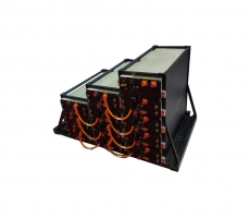
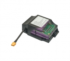
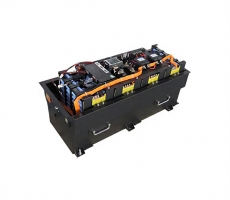
In actual application, according to the needs of a certain brand of
electric bicycle manufacturer, the design and realization of 2 sets of 36V8A·h
lithium manganate power battery protection board in parallel and 10 in series,
in which the single-cell lithium battery protection chip adopts S28241 of Japan
Seiko Co., Ltd. , The protection board is mainly composed of main circuit,
control circuit, shunt discharge branch, filtering, optocoupler isolation and
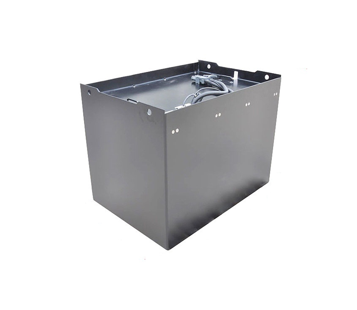
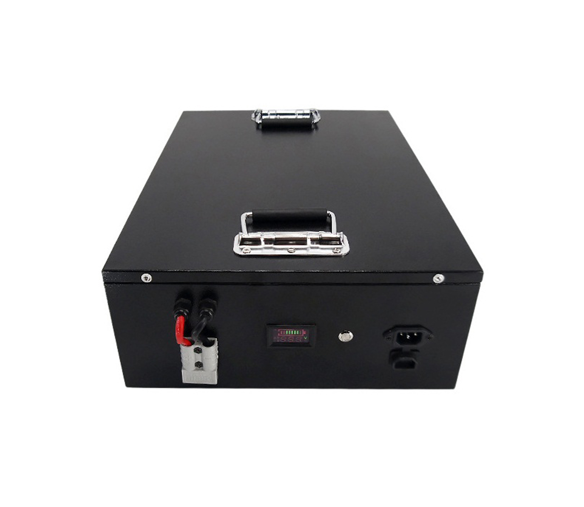
level conditioning circuit, and its basic structure is shown in Figure 7. The
current of the discharge branch is selected to be around 800mA, and a resistor
network is formed by using 510Ω resistors in series and parallel.
Figure 7 Basic structure of lithium battery pack protection board
The debugging work is mainly divided into two parts: voltage test and
current test. The voltage test includes two steps: charge performance detection
over voltage, equalization charge and discharge performance detection under
voltage. You can choose to use a battery analog power supply to replace the
actual battery pack for testing. Because multiple batteries are connected in
series, the test cost of this solution is relatively high. You can also use the
assembled battery pack to test directly, charge and discharge the battery pack
in cycles, observe whether the protection device operates normally during
overvoltage and undervoltage, record the real-time voltage of each battery
during overcharge protection, and judge the performance of balanced charging.
But this scheme takes a long time to test once. When testing the charging
performance of the battery pack, a 3-digit half-precision voltmeter is used to
monitor the charging voltage of 10 batteries. It can be seen that each battery
is within the normal operating voltage range, and the difference between the
cells is very small. The voltage deviation is less than 100mV, the full charge
voltage is 4.2V, and the voltage deviation is less than 50mV. The current test
part includes two steps: over-current detection and short-circuit detection.
Over-current detection can connect an ammeter in series between the resistance
load and the power circuit, and slowly reduce the load. When the current
increases to the over-current value, see if the ammeter indicates a current cut.
Short-circuit detection can directly short-circuit the positive and negative
poles of the battery pack to observe the status of the ammeter. Under the
premise that the device is in good condition and the circuit welding is correct,
the current test can also be carried out directly through the status of the
power indicator on the protection board.
In actual use, considering that the external interference may cause the
battery voltage to be unstable, this will cause the voltage to be over-voltage
or under-voltage for a very short time, which will lead to the wrong judgment of
the battery protection circuit, so the protection chip is equipped with a
corresponding delay Logic, if necessary, a delay circuit can be added to the
protection board, which will effectively reduce the possibility of malfunction
of the protection circuit caused by external interference. Since the switching
devices on the protection board are in an off state when the battery pack is not
working, the static loss is almost zero. When the system is working, the main
loss is the on-state loss of the two MOS transistors in the main circuit. When
the equalizing circuit works in the charging state, the resistance heat loss in
the shunt branch is larger, but the time is shorter, and the overall dynamic
loss is in the battery The group is at an acceptable level during the period of
normal work.
After testing, the design of the protection circuit can meet the protection
needs of series lithium battery packs. The protection function is complete, and
it can reliably protect against overcharge and overdischarge, and at the same
time realize the balanced charging function.
According to the needs of the application, after changing the protection
chip model and the number of series, the power level of the switching devices
and energy consumption components in the circuit, the power lithium battery pack
of any structure and voltage level can be protected and charged. For example,
the FS361A single-cell lithium battery protection chip from Taiwan Fujing
Company can realize the design of 3 groups in parallel and 12 strings of lithium
iron phosphate battery pack protection boards. The final many industrial
products are reasonably priced, and the products have not been repaired after 3
years of market inspection.