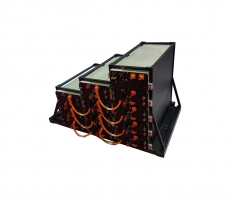
BMS is the core and brain of the lithium battery pack, and its performance
determines the intelligence level and performance of the lithium battery pack.
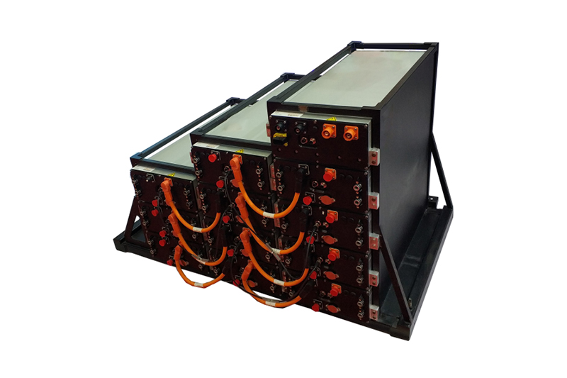
As a manufacturer with nearly 20 years of customized lithium battery R&D and
manufacturing, SES Power is very familiar with BMS. For example, we use
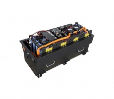
12V100Ah, 12V200Ah, 24V100Ah, 24V200Ah, 36V100Ah, 48V50Ah, 48V100Ah, etc.
Lead-acid replacement, wall-mounted home energy storage, mobile home energy
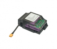
storage, etc., all use high-precision and high-intelligence BMS. In addition to
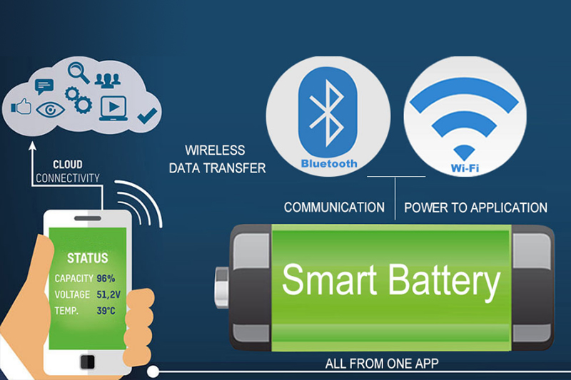
traditional RS485 and CAN communication, we also added Bluetooth communication.
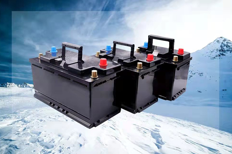
As for special customized lithium batteries such as 12V30Ah, 12V50Ah, 12V60Ah
car start-up batteries (maximum peak current can reach 1500A) using
high-performance lithium batteries, and lithium battery systems normally used in
-40°C environment, because the parameters fluctuate greatly, the design
requirements of BMS are higher.
Below we will explain some of the functions and design concepts of BMS for
you.

The core function of lithium battery BMS is to collect data such as
voltage, temperature, current, insulation resistance, and high-voltage interlock
status of the system, and then analyze the data status and battery use
environment, and monitor and control the charging and discharging process of the
battery system. Under the premise of ensuring the safety of the battery, the
energy stored in the lithium battery system is maximized. According to the
function, BMS can be divided into battery data acquisition, battery status
analysis, battery safety protection, battery system energy management control,
data communication and storage, fault diagnosis and management and other
parts.
1. Battery data collection
Data acquisition includes the acquisition of data such as voltage,
temperature, current, insulation resistance, and high-voltage interlock status,
which can provide BMS with real-time data of the battery system and provide a
basis for subsequent status analysis, control and protection of the battery
system.
The voltage collection includes the voltage of each string of cells, the
total internal voltage Vbat of the battery system, and the total external
voltage Vlink of the battery system. The temperature collection includes the
temperature of the surface of the cell and the tab, the temperature of the
liquid cooling water inlet and outlet, the interface temperature of the
fast-charging pile, and the working internal temperature of the BMS. The current
acquisition mainly collects the current of the main circuit of the battery
system through a shunt or a Hall current sensor, and uses the ampere-hour
integration and other estimation methods to estimate the state of the battery
system. Insulation resistance mainly collects the insulation resistance between
the total positive of the battery system and the box, and the insulation
resistance between the total negative of the battery system and the box. The
high-voltage interlock includes the interlock state of the high-voltage air plug
and the interlock state of the MSD.
2. Battery status analysis
Estimation of the state of charge (SOC) of a lithium battery system: SOC is
defined as the percentage of the battery's remaining charge to the battery's
capacity.
Estimation of the state of health (SOH) of a lithium battery system: SOH is
defined as the percentage of the number of times the battery has been fully
charged to the number of available charges over the battery life cycle.
The estimation of SOC and SOH is the core technology of BMS and the main
parameters for evaluating the performance of lithium batteries in all aspects.
Typical algorithms for SOC estimation include open circuit voltage method (OCV
method), ampere-hour integration method, impedance method, extended Kalman
filter method and neural network method.
At this stage, most BMSs use the optimized ampere-hour integration method.
On the basis of the ampere-hour integration method, cell parameters such as open
circuit voltage, rated capacity at different temperatures, and charge-discharge
efficiency at different currents are added. SOC is corrected.
In order to reduce the SOC estimation error, some BMS manufacturers have
studied artificial intelligence SOC estimation methods: on the basis of the
weighted ampere-hour integration method, real-time OCV estimation is performed
by collecting real-time data (cell voltage, current, temperature, etc.) of the
battery system, so as to achieve dynamic OCV correction SOC.
3. Battery safety protection
When the battery system has faults such as overvoltage, undervoltage,
ultra-high temperature, ultra-low temperature, overcurrent, low insulation,
disconnection of the voltage collection line, disconnection of the temperature
collection line, abnormal high-voltage interlock, etc., the BMS needs to protect
the battery system in time. According to the severity of the fault, protection
measures such as power limitation and immediate power-off are adopted in stages,
so as to ensure that the battery system can maximize the use of its stored
energy under the premise of safety.
In a low temperature or high temperature environment, when the battery
system needs to be charged and discharged, the BMS will first report the cell
surface temperature and the ambient temperature to the system. The system will
heat or dissipate the battery system by analyzing the temperature data reported
by the BMS, so that the battery system is in Charge and discharge at suitable
ambient temperature.
4. Battery system energy management
4.1 Charge Management
The BMS performs a linear look-up table for the charging power MAP of the
battery system according to the current cell temperature and SOC of the battery
system, thereby determining the current maximum allowable charging current of
the system.
When charging, the BMS communicates information with the charging equipment
such as the highest voltage of the battery system, the highest total voltage,
the highest temperature, the current maximum current allowed for charging, the
nominal energy, the SOC, and the current battery voltage, so that the battery
can be charged. The system charges according to the adapted charging voltage,
charging current and charging method to ensure that the battery is fully
charged. At the same time, the remaining charging time is estimated according to
the maximum output capacity of the charger and the state of charge of the
battery system.
4.2 Discharge Management
Discharge management is that the BMS performs a linear look-up of the
10s/30s peak discharge power MAP and continuous discharge power MAP of the
lithium battery system according to the real-time collected temperature and
estimated SOC, and obtains the current 10s/30s peak discharge power value and
continuous discharge power value of the battery system. The discharge power
value is reported to the system MCU.
The MCU compares the motor requested power P1 with the peak discharge power
Pmax and continuous discharge power Pc reported by the BMS. When P1>Pmax,
take the peak discharge power Pmax of the battery system to discharge and time
it, and after the timeout, it will drop to the continuous discharge power Pc to
discharge; when P1
4.3 Balanced management
The main function of balance management is to reduce the voltage difference
between the cell voltages, so as to maintain the consistency of cell discharge
and ensure that the battery system can maximize the use of its stored energy
under the premise of safety.
Balance is divided into active balance and passive balance. Active balance
is when the pressure difference between the monomers is too large, the energy in
the high-voltage monomer is transferred to the low-voltage monomer, so as to
achieve balance; passive balance is when the pressure difference between the
monomers is too large. When it is too large, a resistor is connected in parallel
at the strings of monomers with high voltage, so as to consume part of the
energy and finally achieve the equalization function.
5. Data Communication and Storage
The BMS reports the cell voltage, temperature, total voltage, current, SOC,
SOH and fault alarm data of the battery system to the system through CAN
communication. After the system receives the data, it first displays the
real-time total voltage, current and SOC on the The second is to analyze the
fault alarm information, and then send commands to the BMS through CAN
communication, so that the BMS can protect and control the battery system.
6. Troubleshooting and Management
According to the cell parameters and the function of the battery system,
the corresponding fault threshold table is formulated, including the fault name,
fault threshold, fault hysteresis, fault detection time and response time, as
well as the protection measures taken by the BMS and system protection measures
and other information.